
Our project consists of a glove that has sensors on it. Those sensors send data to an Arduino, which then sends data over Bluetooth to a serial port. Then, the data goes into a program called Max, which generates the sound, which then plays over speakers that are connected to the laptop.
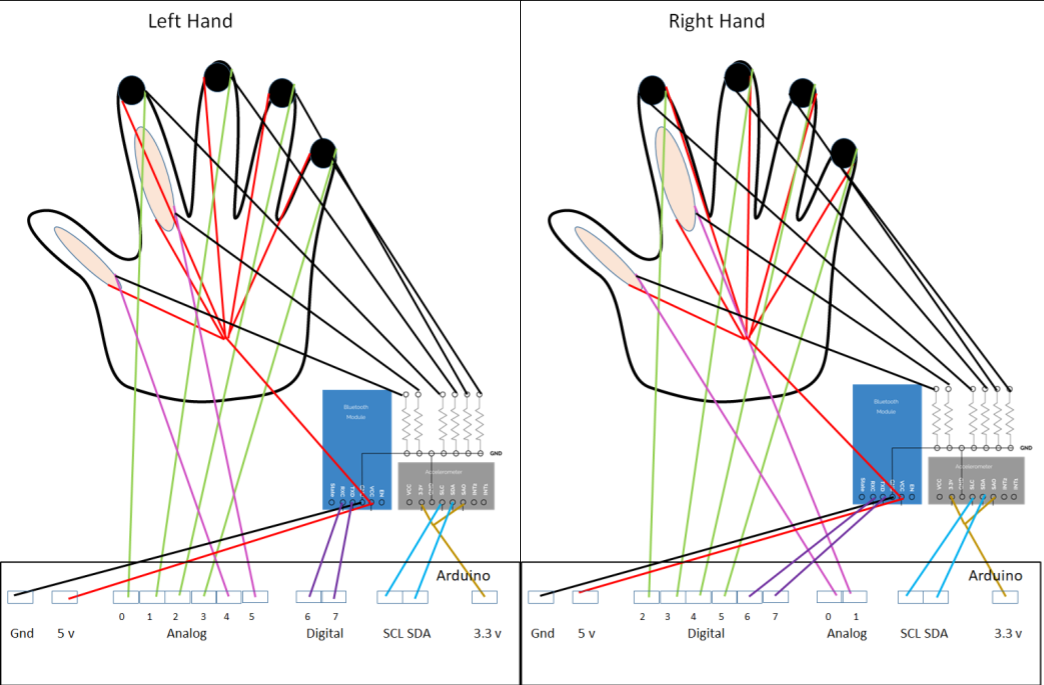
To make the electrical design, you will need to connect the sensors to the Arduino as shown in this diagram. You will probably find it helpful to go through this part sensor by sensor, and connect them according the the diagrams shown, making sure that each one prints over the Serial port, and using the datasheets to troubleshoot if necessary.
We found that it was helpful to use protoboard to organize the soldering of some of the components. As you can see in this diagram, we had the wires from the sensors connect to the protoboard, and go through a resistor to ground. This layout kept the glove as compact as possible. We also put the accelerometer and Bluetooth module here. The accelerometer and Bluetooth module connect through the protoboard by soldering the pins to the protoboard. Here is a decent tutorial on how to solder to prototype board.

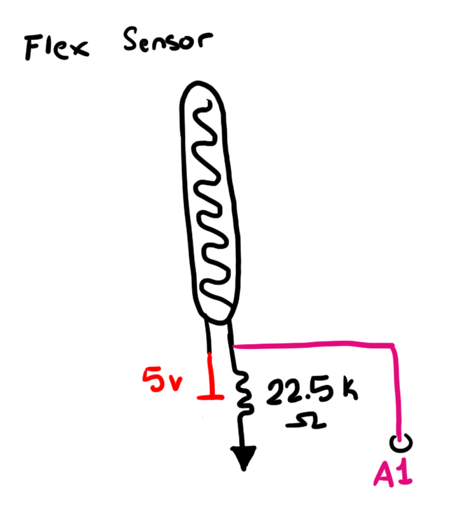
There are 4 flex sensors, and they are located on the pointer finger and thumb joints on the back of both hands. The flex sensor returns a variable value based on how much it is bent. When the flex sensor returns a value past the threshold that determines that it is “bent," a note is played. Based on how much it is bent, the volume of the note changes. The flex sensors have 2 pins, and as seen in the diagram, the flex sensors are connected to power, ground, and an analog pin on the arduino. It should be noted that caution should be exercised when soldering to the flex sensor. Due to its sensitivity, we soldered two wires onto the tabs on low heat and soldered any additional connections to those wires rather than directly to the tabs to prevent overheating.
Datasheet
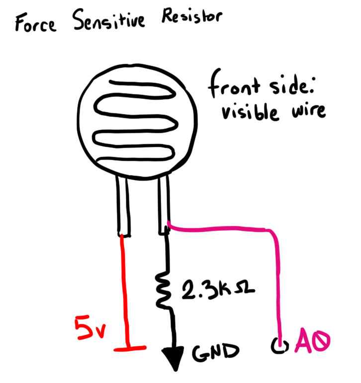
The force sensitive resistors are located on the fingertips of the left hand. The resistors return a value that varies based on the force applied to the resistor. The amount of pressure applied determines the frequency that is outputted. They have 2 pins, and as seen in the diagram, the force sensitive resistors are connected to power, ground, and an analog pin on the arduino.
Datasheet
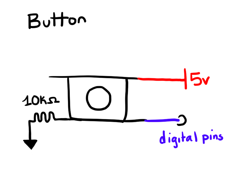
The four buttons are located on the fingertips of the right hand. The push buttons send back whether or not they have been pressed, which is good for sounds like drum beats or sounds that are played when the button is on. They have four pins, and as you can see in the diagram, the button is connected to power, ground, and a digital pin on the arduino. The buttons are placed within finger caps, which are further described in mechanical fabrication.
Datasheet
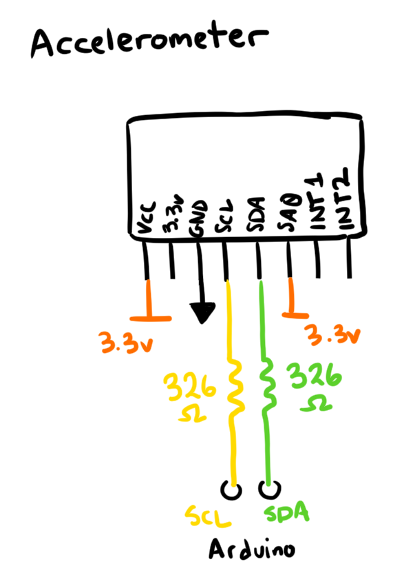
The accelerometer is located on the wrist. It works differently than the other sensors because it uses I2C protocol, which is helpful because the accelerometer sends back a measurement of acceleration in 3 separate axes, which would not be possible using analog pins. This was tricky to get working, but we were able to find the library that made it easier.
Datasheet
Guide that was useful
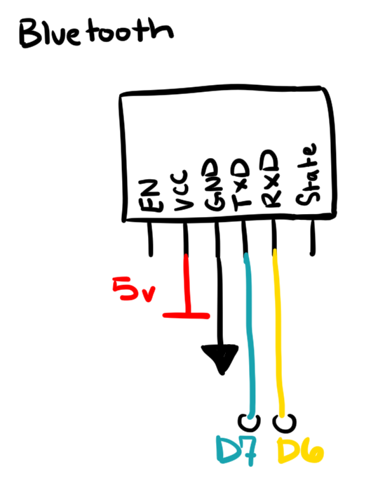
To use the Bluetooth module, first hook it up to the Arduino according to the diagram. The Bluetooth module should have a red light on it that is quickly blinking.
Now, you need to connect to the Bluetooth module with your computer. Go to settings, then click on Bluetooth and other devices, then turn on Bluetooth and click on ‘add device.’ The device is named HC-05, and the PIN is 1234. You may need to remove and re-add the device each time it disconnects. You will know the Bluetooth module is connected when the LED blinks 2 long blinks.
Now in order to see the Bluetooth, go to Arduino and switch the port to the one that the Bluetooth is on. It may take some experimenting to figure out the correct port. Make sure that your sketch includes the Bluetooth code, which is the part of the code that initializes and uses mySerial instead of just using Serial. You may have some difficulty getting the accelerometer working with the Bluetooth code. If you do, make sure everything is wired correctly. Also, good luck.
Once you have found the correct port, if you open the Serial Monitor, the sensor values will be printing out. You can now plug the arduino into a separate computer or power it with a battery, and it should still receive the values.
Once you have soldered all the electrical components together, you can work on the software. The Arduino code is pretty simple, and works by reading in the sensor values and outputting them over Bluetooth. Those sensor values are read by Max, which generates the sound.
There are several different versions of the Arduino code for different situations, more specifically, there is code to run each of the two different gloves both with and without Bluetooth. The reason for this is to both help with debugging sensors before getting Bluetooth working, and to have a backup option if Bluetooth does not work at all. Overall the Arduino code is simple. It imports several libraries for the accelerometer and Bluetooth, and then reads data from the sensors and outputs that data either over “Serial" (normal Serial port with wires), or “mySerial" (wireless Bluetooth). Below, you can see all the versions of our code, as well as links to them on Github.
// Sends data over serial port from left hand
void setup() {
  Serial.begin(9600);
  Serial.println("Setup Done");
}

void loop() {
  // button
  Serial.print(digitalRead(2));
  Serial.print(" ");
  Serial.print(digitalRead(3));
  Serial.print(" ");
  Serial.print(digitalRead(4));
  Serial.print(" ");
  Serial.print(digitalRead(5));
  Serial.print(" ");

  // flex sensor code
  Serial.print(analogRead(A0));
  Serial.print(" ");
  Serial.print(analogRead(A1));
  Serial.println(" ");
}
// Sends data over serial port from left hand
void setup() {
  Serial.begin(9600);
  Serial.println("Setup Done");
}

void loop() {

  // code for force sensitive resistor
  Serial.print(analogRead(A0));
  Serial.print(" ");
  Serial.print(analogRead(A1));
  Serial.print(" ");
  Serial.print(analogRead(A4));
  Serial.print(" ");
  Serial.print(analogRead(A5));
  Serial.println(" ");

  // flex sensor code
  Serial.print(analogRead(A2));
  Serial.print(" ");
  Serial.print(analogRead(A3));
  Serial.print(" ");

}
// prints data over Bluetooth from right hand

#include <SoftwareSerial.h>>

// set up bluetooth code
int rx = 6;
int tx = 7;
SoftwareSerial mySerial(rx, tx); // RX, TX

// wire allows communication with the accelerometer using I2C
#include <Wire.h>

// needed for communicating with this particular accelerometer
#include "SparkFun_MMA8452Q.h"

// create instance of the MMA8452 class for accelerometer
MMA8452Q accel;

void setup() {
  Serial.begin(9600);
  Serial.println("test"   );
  mySerial.begin(9600);

  // check if accelerometer is connected
  while (accel.init() == 0) {
    Serial.println("Not Connected");
    delay(200);
  }

  Serial.println("Done");

}

void loop() {
  // accelerometer code
    // Acceleration of x, y, and z directions in g units
    float ax = (accel.getCalculatedX());
    float ay = (accel.getCalculatedY());
    float az = (accel.getCalculatedZ());
    mySerial.print(ax);
    mySerial.print(" ");
    mySerial.print(ay);
    mySerial.print(" ");
    mySerial.println(az);

  // button code
  // button 1
  mySerial.print(digitalRead(2));
  mySerial.print(" ");
  // button 2
  mySerial.print(digitalRead(3));
  mySerial.print(" ");
  // button 3
  mySerial.print(digitalRead(4));
  mySerial.print(" ");
  // button 4
  mySerial.print(digitalRead(5));
  mySerial.print(" ");

  // flex sensor code
  mySerial.print(analogRead(A0));
  mySerial.print(" ");
  mySerial.print(analogRead(A1));
  mySerial.print(" ");

}
// prints data over Bluetooth from left hand

#include <SoftwareSerial.h>>

// set up bluetooth code
int rx = 6;
int tx = 7;
SoftwareSerial mySerial(rx, tx); // RX, TX

void setup() {
  Serial.begin(9600);
  mySerial.begin(9600);

  Serial.println("Setup Done");

}

void loop() {

  // code for force sensitive resistor
  mySerial.print(analogRead(A0));
  mySerial.print(" ");
  mySerial.print(analogRead(A1));
  mySerial.print(" ");
  mySerial.print(analogRead(A5));
  mySerial.print(" ");
  mySerial.print(analogRead(A4));
  mySerial.print(" ");

  // flex sensor code
  mySerial.print(analogRead(A3));
  mySerial.print(" ");
  mySerial.print(analogRead(A2));
  mySerial.println(" ");

}
For our glove, we use Max/MSP for sound generation. Max is a visual programming language that uses objects and messages connected to each other in a signal flow diagram to execute functions. These collections of objects are known as patches, and the full program is known as a patcher. While it still follows the same logic as other programming languages, it is designed for and especially popular in audiovisual projects. (MSP is short for both Max Signal Processing, the audio side of things, and also the creators’ initials; I will hence refer to it as just Max but recommend including MSP in any web searches).
You first step to using Max is downloading it. As of writing this, we’re using Max 8--anything made in past versions is compatible with new versions, though the interface may appear slightly different. Max has a 30 day free trial, and after that you can purchase monthly, yearly, or permanent licenses with discounts for students. Download at the Cycling ‘74 website here.
Once you download and open Max, you can go the easy way and just copy the text from Github and select “New from Clipboard" from the “File" menu.
It should look like the image on the right.
I have organized and grouped each component into blocks. The dark box has unused parts you can switch out. Feel free to add as you would like!
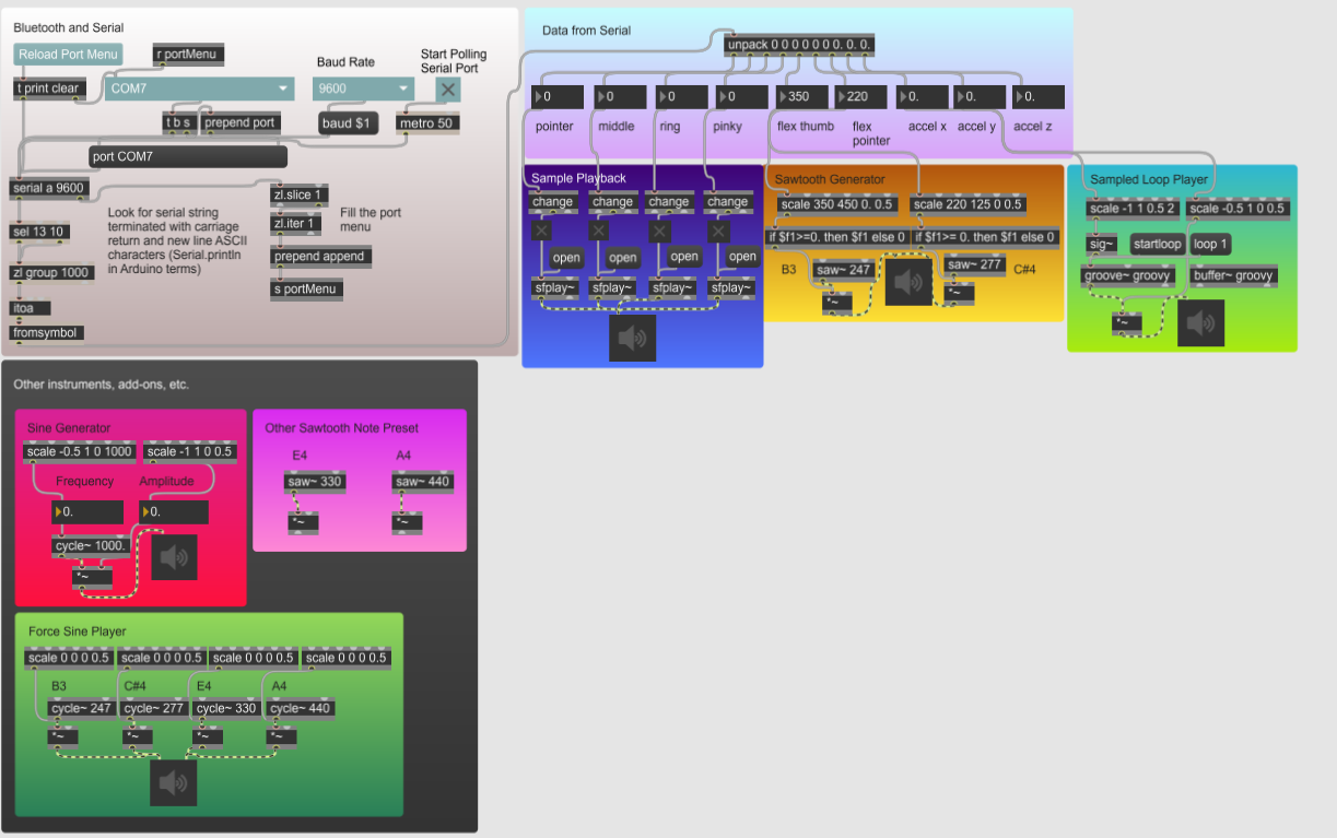
Just like other types of programming, a lot of this is done with the help of others. The first part of the patcher, which connects Bluetooth, is courtesy of Luke Woodbury from the Max forums.
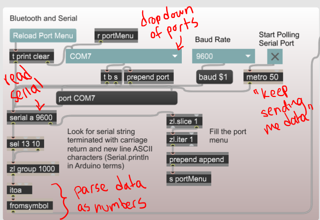
Your Arduino can send and receive messages to and from the Serial monitor. Serial data is sent one bit at a time and allows communication between the Arduino and a computer--and from there, the computer and another program on the same machine.
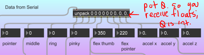
Using the serial object in Max, you can access Serial data being sent through an Arduino. I explain more about how this works in the picture here.
Your Arduino code should be sending the sensor values as numbers. The unpack object separates the list of values from the Serial monitor into numbers that can be parsed individually. When running, the values will change in real-time. This code is working for our right hand, which has button fingertips.
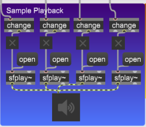
In the image below, the “x" buttons are toggles, which are turned on each time they receive a 1 and off when they receive a 0. If directly connected to the number box, they would trigger every single time they received a 1--multiple times a second. The change object helps to only trigger the toggle when there’s a transition from 0 to 1. The toggles then connect to the sfplay~ object, which will play a sound file out of the speaker (ezdac~). When you click the open message, you can select an audio file from your computer that will play every time you turn on the toggle for as long as your patcher is open. This allows you to play 4 different sounds using the buttons (you can play them at the same time as well).
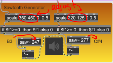
The flex sensors play set notes when flexed. The saw~ object plays the frequency specified by the number in the box (If you want to change notes, check out this table). The flexing of the sensor controls the *~ object, which is an amplifier. Our goal is that an unflexed sensor will play no sound, and the more you flex, the higher the volume. As such, the minimum should be 0, and the maximum is 0.5 volume--so not to be obnoxious.
This is accomplished using the scale function, which you may need to adjust to suit your individual flex sensor values. The first value is the minimum input, and second is maximum input. Third is minimum output and fourth is maximum output. As such, I expect that past the point where our first flex sensor reads 350 up until 450, it should increase the volume. The second flex sensor actually decreases its value when flexed, which means that the maximum value is a smaller number! Max easily adjusts to this, but it’s good to know you can do that.
The if statement exists because there’s a chance you’ll get a number lower or higher than your scale value expects. The scale object will still output a value along the same proportion, but it might even send out a negative number! Without the if to filter out values outside of our desired range, the saw wave played constantly and unpredictably. It could be placed before the scale, but we chose to place it after so that it wouldn’t need to be adjusted to different flex sensor values.
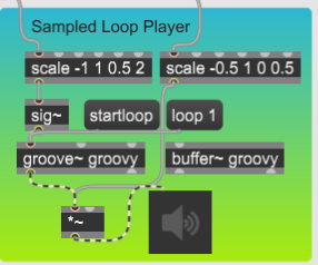
The accelerometer, in our case, is only implementing the x and y axes in our sample loop player. This instrument uses the groove~ object to play a loopable sample over and over again. Using the Max File Browser (concentric circles on leftmost toolbar) load a file into the Max filepath. Then, click and drag it to the buffer~ object. It will hold the audio file while the patch is open, and the groove~ object will replay it. The scale objects control the speed and volume of the loop, respectively. When the x-values change, the sound will speed up or slow down. When the y-axis changes, it gets louder or quieter.
Alternatively, you can connect the accelerometer to the Sine Generator instrument. Just take the number values and draw cords to the scale function.
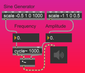
In the image below, the cycle~ object generates a sine wave with initial frequency 1000. You can replace it with saw~ for a sawtooth wave, tri~ for a triangle, or rect~ for a pulse. You can also further explore modifying waveforms in Max using available documentation and connect it to the same framework.
Similarly to the saw~ function, part of this instrument involves controlling the volume. However, the pitch is also controlled by the x-axis change. While the sine wave (cycle~) is initialized with a frequency of 1000, it will adjust based off of the sensor.
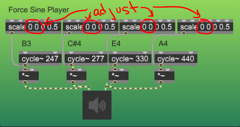
For the glove with force sensor fingertips, you should replace the Sample Playback instrument with the Force Sine Player. The force input adjusts the volume and plays set frequencies that you can adjust in the cycle~ object. My scale object starts with no set minimum and maximum as your force sensors will likely have individualized values. Make sure you fix them before you patch!
When it’s time to switch from coding to playing with the program, click the “lock" in the bottom left corner.
There’s a lot to mess around with; if you get lost, check out the Cycling ‘74 website and forums for more information. Thanks so much, and happy patching!
If you want to hear my thoughts on the how and why of Max, and my trials and tribulations, check our my reflection.
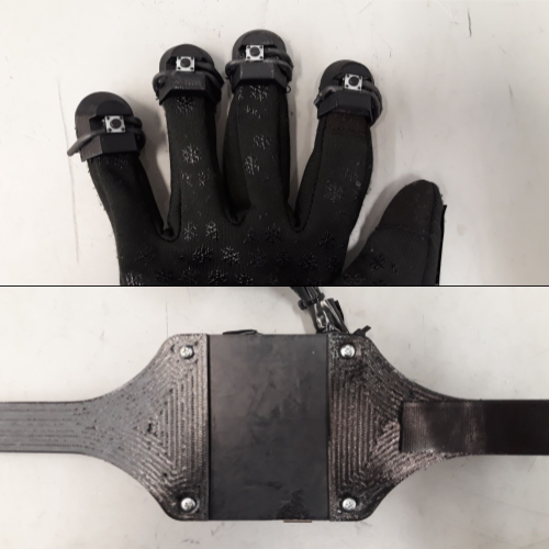
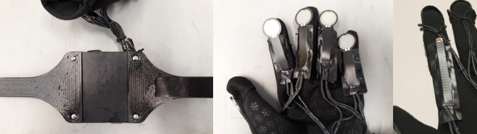
In order to hold the Arduino, buttons, and batteries, we need to 3D print a few casings. The CAD files for the finger caps (to hold the buttons), and the battery case are attached below as STL files. We have also attached our SLDPRT files if you would like to modify it according to your needs (you will need Solidworks 2018-19 or later). Open the STL file in your slicer program of choice and print in PLA. You will need 2 battery cases (one for each glove) and 4 finger caps.
You will also need a case to hold the Arduino onto the wrist. We used the following open source model by ZygmuntW on Thingiverse. You also need to print the wristband pieces (x2) (file found below) in TPU so it will be flexible.
velcro_wristband.SLDPRT
velcro_wristband.STL
coincellbatterycase.SLDPRT
coincellbatterycase.STL
coincellbatterycover.SLDPRT
coincellbatterycover.STL
fingercap2.STL
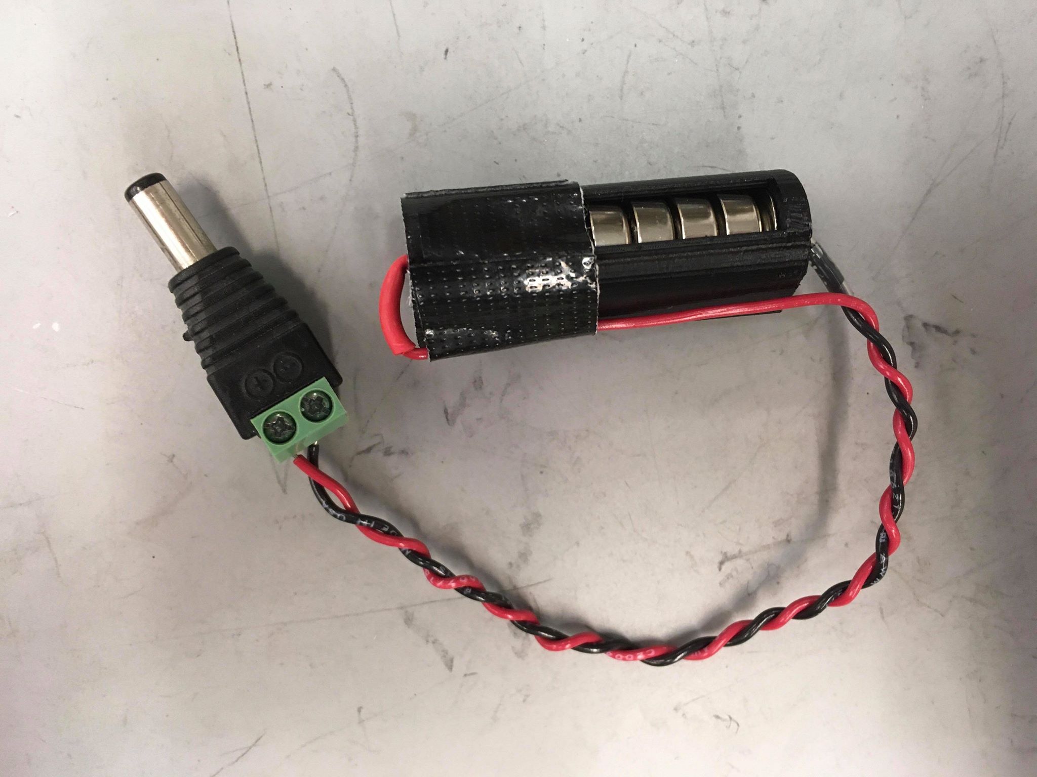
To assemble the battery case, solder a red and black wire to the sharp part of the metal pushpin. It helps if you are able to snip off a bit of the tip. Cover the soldered joint with heatshrink and apply heat. Thread the wires through the holes of the case so that the flat parts of the push pins are inside the case. Insert 7 coin cell batteries into the case and securely tape shut. Check if the voltage is around 10V with a multimeter. Attach the ends of the wires to the 5.5mm x 2.1mm plug and screw closed so you get a good connection.
Once you have all your pieces printed, you can start assembly. Insert the Arduino into the case and line up the wristband pieces with the holes on the back, and screw together using the 4-40 bolts.
You will need to sew several components to the base fabric gloves. Sew the 4 finger caps onto all the fingers except the thumb on the right handed glove using the needle and thread. Encase the four flex sensors in electrical tape and sew (through the tape) one sensor on the index finger and thumb (for both the right and left hands). Using the same method, tape the four force sensors and sew to the other four fingers of the left hand. When sewing, it is important that you do not sew the glove closed, and check to make sure that the sewing does not impede movement of the hand.
Superglue the velcro to the wristband, and add a bit to the back of the battery case and the top of the Arduino case. You will also need to superglue the buttons to the channel inside the fingercaps.
Finally, plug in all the wires into the Arduino according to the above circuit diagram, and add a bit of tape to the back of the protoboard to hold it on top of the Arduino case.