Menu

Mechanical

The CAD, design, and fabrication of our board

The Deck

Design

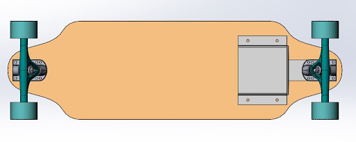
It all started with a pen and paper - we wanted to create a unique shape to give our users a different experience and to separate ourselves from the other motorized skateboards and longboards on the market.

After some further research and discussion with longboard riders, we decided to go with a more conventional board style to create the most comfortable and functional experience for the rider, however, we decided upon a shorter head and tail to give us the most room for fitting electronics, while keeping in mind the locations of the wheels.

The First Board

Our first board prototype began in Solidworks, and was modified to fit a piece of scrap three-ply plywood we found. This limited our board length, giving us a board 34” long and 10” wide. It was acceptable for prototyping, but we were determined to find a longer, nicer piece of plywood for our final design.

The first iteration of our board had a couple problems: first and foremost, it was shorter than ideal. The width was great for us, as it allowed us as less experienced longboard riders to get around fairly easily. However, the scrap wood used was not great quality - the three-ply plywood was not strong enough to endure a multitude of rides from members of the team. Though it can fix anything, we decided duct tape was not the optimal fix for our board cracking in multiple places, and moved on to our second iteration.

The Final Deck

Our first mission was to find the appropriate wood for the job. Typically, longboards are made with many thinner layers of wood that are glued together and formed into the ideal shape. Due to constraints on time and budget, we opted for a material that would achieve something similar - 10-ply plywood. Our ¾” thick birch stock was then put on our shop’s ShopBot , cut out to 40” long by 10” wide, filleted, and sanded with lots of love until we reached our final, smooth shape. To ensure cleanliness and the preservation of the board, we coated the deck with polyurethane to seal the board and protect it during future use.

The Drive Train

The Belt Drive

Our drivetrain is a relatively simple set of timing belt drives, one for each of the rear wheels to generate the desired rear-wheel drive. The pulleys were ordered from McMaster-Carr here (https://www.mcmaster.com/timing-belt-pulleys), and the belt itself was also from McMaster-Carr, linked here (https://www.mcmaster.com/belts). The pulleys used were the XL Series Lightweight Timing Belt Pulleys with an OD of 1” and 2”, to create a 2:1 gear ratio in our drivetrain. The timing belt was the XL Series Timing Belt, with a width of ¼” and an outer circle length of 15”, to give us about five inches between the center of each pulley.

Implementation
The ordered pulleys worked great, but we needed to get the larger pulley to fit around the truck structure - it was either this or somehow modify the fairly expensive trucks, so we opted to modify the pulleys. The pulley consisted of a central metal core to fit the shaft of whatever is holding the pulley, and a plastic outer piece with the timing belt teeth. We used an arbor press to try and remove the press-fit metal core, but only broke the pulley.

Disappointed but not discouraged, we came up with a new solution - try and freeze the pulley, as metal shrinks when it is cold. With permission from the bio/chem labs at our school, we placed the pulley in the -80 degrees Celsius freezer (-112 deg Fahrenheit) for about 24 hours. Hopeful, we removed the pulley, put it in a cold bag with ice, and transported it to the arbor press in the machine shop. Once again, the we had no luck - the pulley snapped, though it was cleaner than the last break.

Out of time and money, we decided to try 3D printing our own pulleys by utilizing the CAD McMaster-Carr provides. Using the same files, but removing a 1.25” circle from the center of the pulley, it proved to be a success. The pulleys worked and even matched our board’s color scheme.

In an attempt to increase the surface area between the wheels and the pulleys, we designed a pulley with a dome to match the curvature of the inside of the wheels. We also increased our larger pulley outer diameter for the final print to be 2.53”, to once again increase our gear ratio and get more torque out of our motors.
The Motor Mounts

This component of our board went through the most iteration, and as a result has had the most success out of all the drivetrain parts. Our first plan was to create a small structure that would mount the motors directly to the bottom of the deck, as we had seen a couple of other online DIY attempts utilize this method. Once we had our first deck built and the trucks attached, we started to learn how to ride a longboard. It was only then we realized that to turn, the trucks turned separately from the board, which would cause the timing belts to gain and lose tension, rendering the drive train ineffective. We owe this realization to a random encounter with an upperclassmen, Ben, for spotting this and saving us a lot of time and trouble. Our next plan of action was a sheet metal casing that would attach to the trucks. Excited to build, we jumped right into the fabrication of the motor mount. The sheet metal tools available to us, however, proved incapable of create the shape we modeled in SolidWorks.

Following this, we created a thin plywood version of the motor mount using the laser cutter. Some quick laser-ing and a bit of hot glue later, we were ready to roll…or so we thought. There had been a brief oversight, where mounting the system between the trucks and the deck would cause the same issue as mounting the motors directly to the board. In this design, the pressure of the rider and the deck itself would not allow for movement in the system. With less than twelve hours until our MVP was due, we had to think of a new solution, and fast.

Our MVP model consisted of layers of laser cut plywood that press fit onto the trucks directly. These pieces supported a small box that housed the motors at approximately the width of the wheel pulleys, which was another problem in our previous models. We opted to have our MVP model only house the motors instead of the addition of the large ESCs, which proved useful in making it fit the constraints of the truck width.

The last iteration of our motor mount uses most of our MVP model’s design, but with additional slots for the motors to sit, to allow us to tension our belts as they stretch over time.

What's Underneath

What good is a longboard if the electronics aren’t protected from the elements? We built a laser cut casing for the electronics under the board, similar in style to the box that houses the motors. While the ideal version of our project would not use thin plywood to protect the electronics from damage, we ran out of time and money to create an alternative. Future ideas include building a carbon fiber casing for under the board, or actually integrating the components directly into the board with a thicker deck.