Menu

Electrical

Details on the circuits and motors powering our board

Components

Specs

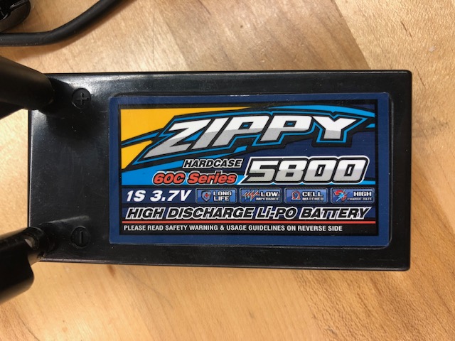
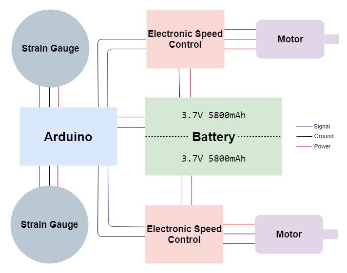
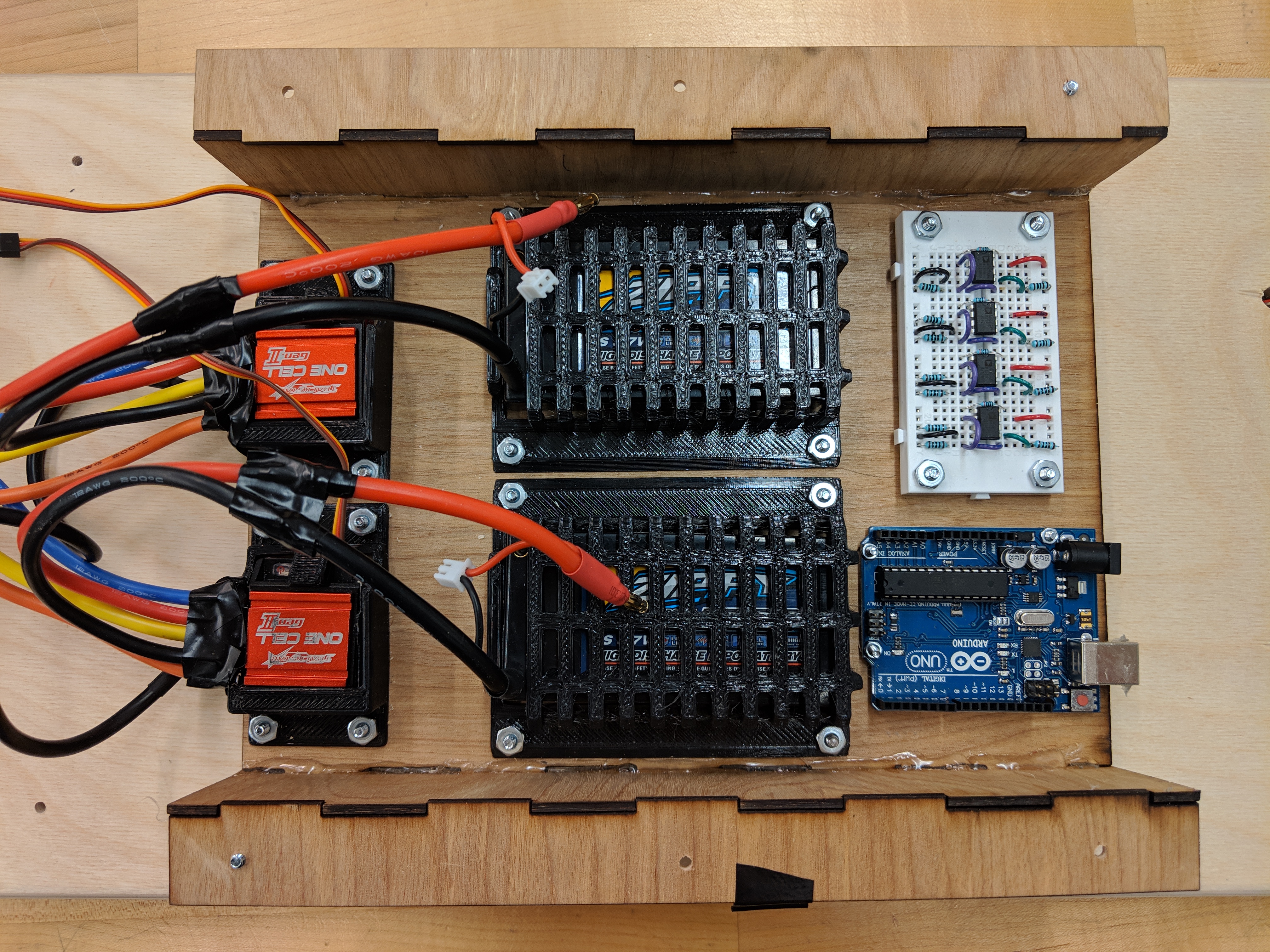
Our board is powered by two one-cell (3.7V), 5800mAh Lithium-polymer batteries; the power from these batteries is regulated and transferred to the motors using two Turnigy Trackstar One-Cell Electronic Speed Controllers (ESC). The brushless DC motors used in conjunction with the ESCs are also from the Turnigy Trackstar One-Cell line, with these specific ones operating between 80A and 120A, with a KV value of 6580. We used a standard radio receiver and controller for the RC stage, and the strain gauges for the pressure stage were taken directly from a bathroom scale. The brains of the board are controlled by an Arduino Uno microcontroller.
Connections

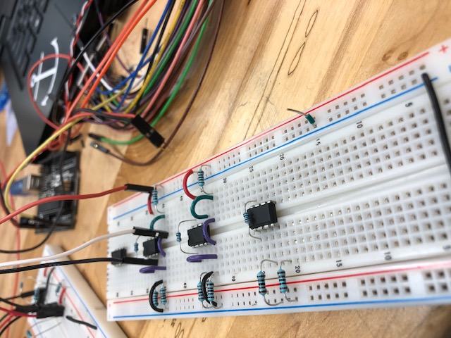
The components were wired together with a combination of soldering, male/female pin connections, and solderless breadboard circuitry. Initially, we sought to develop a PCB to connect all of our components, but the need for thicker 12-gauge wires, lengthy connections, and large motor components outweighed the benefits of a PCB. We used various types of connectors throughout the system, varying from regular header pins for signals to heavy-duty banana plugs for transferring large amounts of current. The wiring of the 12-gauges proved to be difficult to apply to the pads on the motors and ESCs, and at one point towards the end of Sprint 3, we made a connection mistake which resulted in of the ESCs going up in a puff of smoke. Upon inspection and safety checking, we discovered that the ESC’s connection to the battery had shorted, and the radio receiver was wired incorrectly. This led to us being even more careful and deliberate with our connections not only to avoid frying another piece of equipment, but to maintain team safety above all else.

RC Control

ESC Calibration

Electronic Speed Controllers are incredibly useful tools for communicating with and controlling brushless motors. Unfortunately, they can be difficult to work with. They need to be programmed before use, but don’t usually have any interface for doing so other than a single button used as both a power switch and programming control. Also, with our luck, the manual for our ESCs was poorly translated from Chinese. Luckily, we figured out the sequence of button presses needed to calibrate the high, low, and neutral speed signals of the motors using the RC controller and receiver.

Implementation

With the ESCs calibrated to the RC controller, all we had to do was replace our clunky, outlet-wired power supply with batteries. With everything connected, all it takes to get the board moving is the flip of a switch! Actually calibrating the ESCs, however, took almost a sprint and a half just to get them to turn on into the right mode, and another sprint and a half to get them to connect and control the motors with a radio receiver and controller.

Pressure Control

Building the Rig

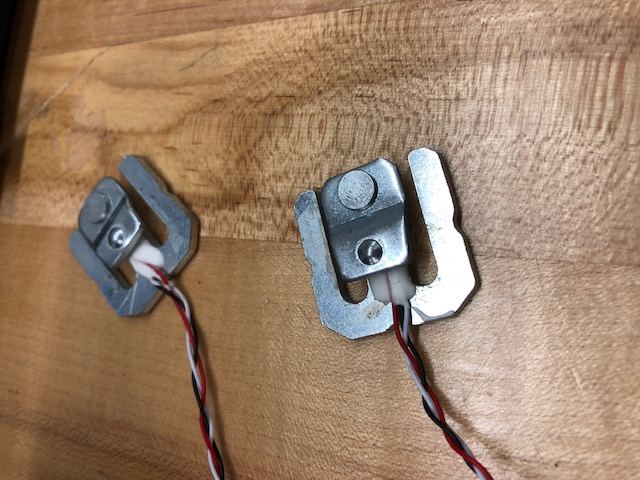
Our pressure sensors consist of four strain gauges taken straight out of a bathroom scale. This creative solution is already calibrated to reading human weight, and scales contain a Wheatstone bridge to calibrate the four strain gauges for calculating weight properly. We put each individual strain gauge into a separate Wheatstone bridge, and turned up the output with an instrumentation amplifier (in this case, an AD623) - this allowed us to both amplify the resistances from each as well as measure differences in stance. We set up the four sensors so that two would measure each front and back of a foot, so that we could measure a differential not just between the front and back foot, but a differential between leaning laterally left and right to filter out noise from turning. The strain gauges would sit inside the board with a plywood plank on top, large enough to detect changes in a typical human foot. Once these values were read, the wires from the strain gauge would feed through the board into the Wheatstone bridges and amplifiers to the Arduino to be read in as difference values.

Testing the Sensors

In theory, all of the pressure sensing seems quite simple, however, the implementation required Wheatstone bridges and op-amps to have extremely accurate wiring at a small scale. After requiring relatively precise resistor values to provide the desired function, multiplying that by four generates a quite complicated circuit. We used an Analog Discovery and the WaveForms software to test output from each sensor before plugging it into an Arduino (Noah has fried five of them this semester already). Once each sensor is up and running, it’s ready to be wired onto the board. While this is best case scenario, unfortunately, only one of the four strain gauges we extracted actually worked the way we needed it to, and the op-amps we used were often of questionable working order. The small wires of the strain gauges proved difficult to manage, however, we were able to generate four individual working circuits to measure resistance change and amplify the signal.