Mechanical Design
Overview
We created two finger boxes to house our two fingers as they independently move along a gantry system. Each finger box is an acrylic housing mounted on T-slot linear bearings that contains a servo, which drives a four bar linkage finger. The back of each finger box is attached to a timing belt driven by a stepper motor, so it can move linearly on the T-slot framing along the length of the piano. The servo motors are secured within the finger boxes, and the fingers hang out from the front of the boxes.
After considering many designs and sketch-modelling a few, we produced a CAD of our finger box in SolidWorks. While making the computer model of our physical system, we were careful to check for interference and proper fits. When designing this piece, we kept design for assembly principles in mind. Our box is assembled mostly using mostly bolts in T-slots, along with chemical acrylic welding in select areas.
Support Design
The art-duino gantry was created out of 1.5” T-slotted aluminum framing and laser cut acrylic pieces. The T-slot framing was assembled to have two pieces on the ground providing support, and a second longer piece that was elevated and spanned the length of the piano. Having the elevated framing allowed clearance for the finger to travel over the keys. Stepper motors are attached on one end of the top piece, using laser cut 3/16” acrylic for added stability. On the other side of the top piece are a pair of shafts that hold pulleys. A GT2 timing belt is strung between each servo and its respective idler gear. We attached one finger box to each belt on the gantry.
Towards the end of the meeting, Daniella came to help us pick a way to assemble our physical system. I’m looking forward to our meeting tomorrow.
Finger Box Design
Bearing/Overall Structure
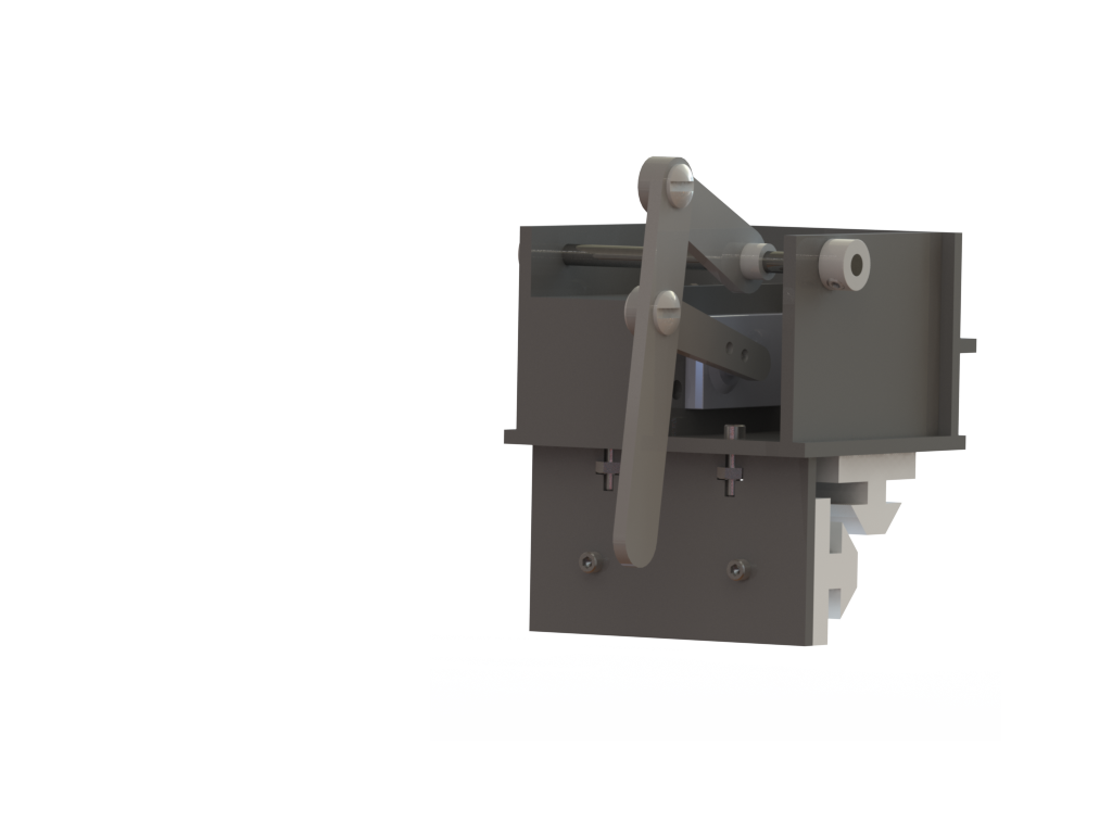
The basic structure of our finger box is a box without a lid or front wall; only a bottom, two sides and a back. The four main walls of each box are acrylic welded together. The back of one box extends lower than the back of the other, as the belt it needs to attach to is lower than that of the other box. Each box also has a lower front plate. This plate is present to prevent rotation of the finger box and to provide more stability than is present with a single bearing. This lower front piece is attached with bolts to the bottom plate of each box, to allow for adjustment so that the bearings are properly aligned with the T-slots.
Between the front top corners of the side walls is a shaft, which holds part of our four bar linkage. Inside the box is the housing for the servo motor. Each servo is placed against the back and left walls of the box, when looking at the box from the front. The servo is bolted to the right side of its housing compartment, the top of its housing compartment is bolted to the back wall of the finger box, and the front of the servo housing is simply slid into its place. The three walls of the servo housing are also acrylic welded to each other, but the housing is not permanently fixed to the finger box. This allows us to remove the servo without needing to break acrylic welds. Bolted to the back of each finger box is an acrylic plate that holds the belt.
The finger box interfaces with the T-slot framing through delrin bushings contoured to the shape of the T-slot framing. Both finger boxes have a front and top bearing, and the finger box with the longer back has a third delrin bushing.
Finger
To play a key on the piano, we used a four bar linkage driven by a servo motor. More specifically, we used a planar parallelogram linkage, with the foot extended off of the coupler link. The input link is attached to the servo, and the output link is attached to a shaft running across the top front edge of the box. By choosing this design, the linkage achieves near vertical movement, as it sweeps from the up to down positions. Using a four bar linkage with a short lever arm also preserves the force output of the system. This is critical when designing a robust system that has to overcome the resistance of the piano keys.
Belt
Components of our gantry system are attached using a GT2 Timing belt. Each belt was cut to snugly fit around its stepper motor and its respective idler gear on the other side of the gantry. The ends of the belts were held together on the backs of the finger boxes, where they were placed teeth-to-teeth and clamped tightly between two pieces of acrylic, using nuts and bolts.
UI Housing
For mechanical and aesthetic reasons, we designed a box to contain our long motor wires, power supply wires, Arduino, and motor shield. The top of this box is a piece of acrylic with an LCD screen and two buttons. The rest of the box is simple, four walls and one bottom. Some extra pieces of acrylic are on the sides of the box, they add designs similar to the designs on our finger boxes. The entire UI box is acrylic welded together with the exception of the lid, which is held down by four bolts, allowing us to adjust the wiring after construction as needed.
There are four holes in our UI box that serve as ports for wires. Two are power supply lines, our 5V power supply for the servo motors and our 12V power supply for the motor shield. The third hole allows us to plug our Arduino in to a computer. The final hole is in the back of the box and the wires for both servo and stepper motors run through it. Our excess wire is neatly rolled and contained within our UI box.
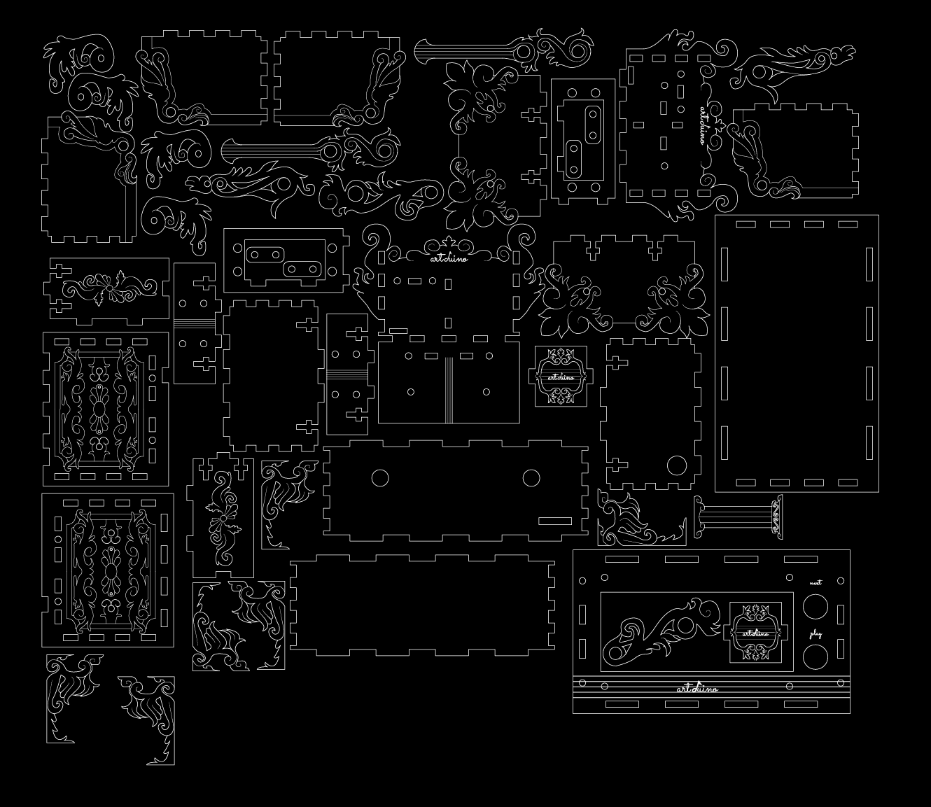
Aesthetic Choices
After designing and testing all pieces in solidworks and in a physical form, we exported the Solidworks drawing to Adobe Illustrator for easier aesthetic modification. Our aesthetic was inspired by the ornate style of Rococo-era France. We began by sketching over printed designs, then moved onto modifying the Illustrator file. A five bar staff was a common theme throughout, alluding to the musical purpose of the machine we built. The rastered designs added interest to otherwise large flat areas, and the vector cut edges produced interesting contours, and echoed the artistic touches included on many ornate pianos to this day. We also added a three dimensional aspect to the UI housing by acrylic welding ornamental pieces onto the structure of the piece, and creating a wide foot to the end of our finger.