Electronic Design
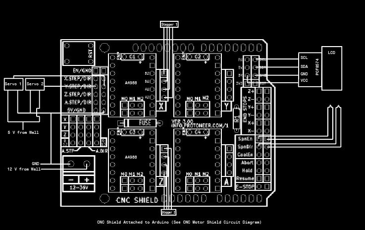
Our electrical system involves two power sources, a single Arduino, a Version 3 CNC motor shield, two A4988 stepper motor drivers, two stepper motors, and two servo motors.
Stepper Motors
The CNC shield requires a power source to power the stepper motors. We connected a 12V wall power supply for this. We set the motor drivers to have an output current of around 1.5A, to power the steppers without frying any boards or chips. When we were working with a breadboard, motor driver, and Arduino in earlier iterations, we had it set to 2A to maximize efficiency, but this produced an extensive amount of heat, and so we lowered it for the safety and longevity of our system.
Servo Motors
We connected the servo motors to the Y step and direction pins on the motor shield, which connect to the digital pins 3 and 6 on the Arduino. Both use pulse width modulation to get analog results through digital means. Powering the servos through the 5V pin on the CNC shield worked very well for a single “finger” structure. Using a 12V supply for a 5V pin released 7V from each servo as heat. When we tried implementing a second structure, the system overheated. Because of this, our system would keep resetting itself, and it seemed like nothing was following the program. We initially thought our servos were broken, because we had several previous issues with broken servos derailing our functionality. However, when we tested the servos with a separate power supply, the system functioned normally. We then used a separate 5V wall power supply for the steppers.

LCD Screen
Our user interface uses an LCD2004 screen with an I2C bus. The LCD screen can display 4 rows of 20 characters, and each character is an 5x8 dot matrix. The I2C bus allows us to download a library and then send information using serial to the LCD screen. This reduces the number of pins needed on our Ardiuno, and allow for more compact housing.