Head and Gimbal
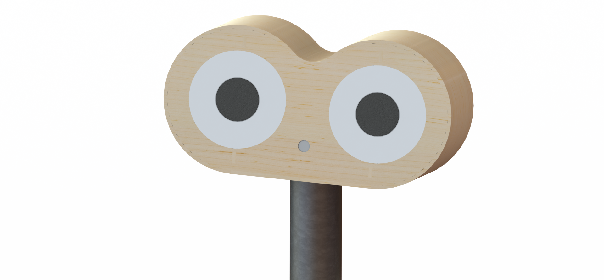
Eye-Robot’s head serves to house the Camera, Speakers, and Microphone that let our user interact with the world around them, in addition to the Raspberry Pi that serves as our robot’s brain. Eye-Robot’s entire head is capable of panning and tilting to move the camera while giving people interacting with the robot a clear idea of where our user is looking.
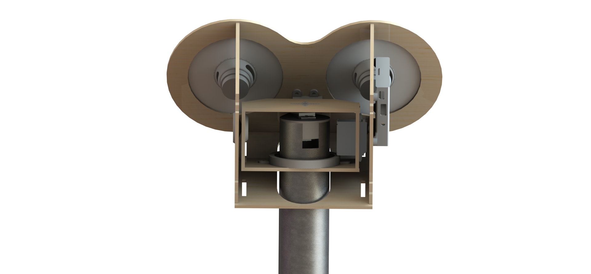
The head assembly is mostly bonded together, with the ‘head wrap’ that makes the sides and top of the head and the back plate both screwed on to give easy access. The head’s pan mechanism consists of a hobby servo mounted into the PVC “Neck” via a 3d-printed adapter. The pan servo’s horn is pressed directly into a laser-cut profile for it, allowing for robust torque transmission. A custom 3D printed ball bearing forms a second point of contact between the head and the neck, making sure that should the robot hit its head the resulting load will not be transferred to the body through the pan servo.
The tilt assembly consists of a servo mounted to the pan mechanism and a coaxial shaft and bearing. The servo drives the head’s tilting through another custom laser cut adapter while the 3D printed shaft and skateboard bearing support the other side of the head while ensuring smooth motion. The combined effect is that the head of the robot can smoothly and easily turn to look in the desired direction
Drivetrain and Body
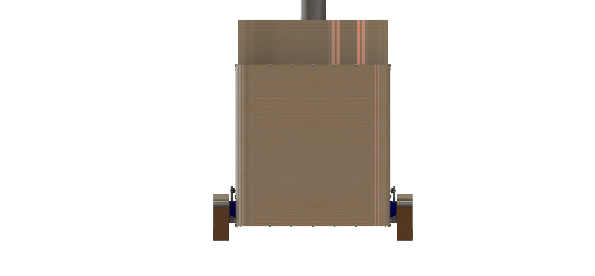
The body houses the remainder of the robot electronics, including the Arduino, motor controller, and batteries. It also serves as a structural path between the robot’s drivetrain and head. Eye-Robot is designed to be easily accessible and maintainable. The body’s large front plate is easily removable via a few screws to allow and the cavernous space inside provides plenty of room to work.
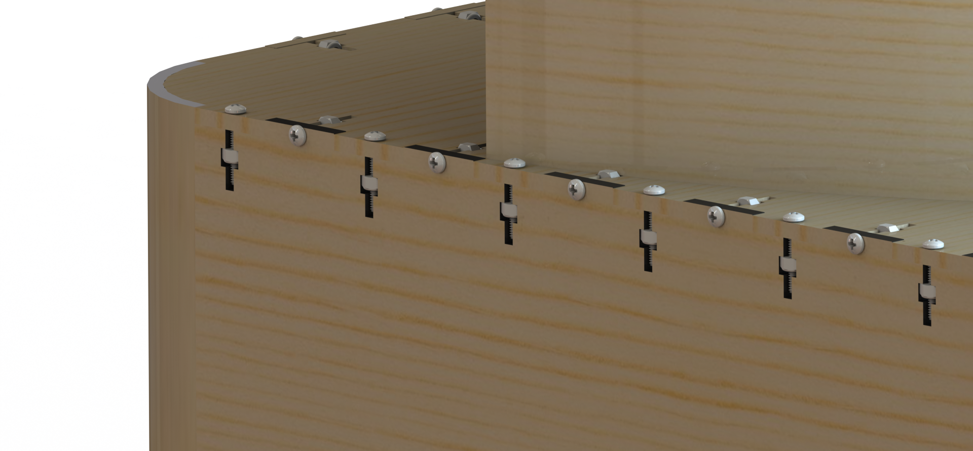
The body construction of laser-cut 1/8 inch plywood with Mortise and Tenon joints and T-slot fasteners running down every edge allows for a stiff, robust system that can take dings and crashes.
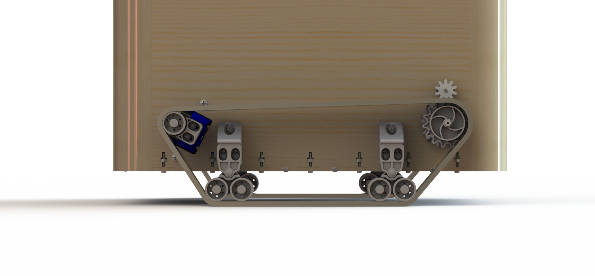
The drivetrain was designed with robustness and ease of maintenance in mind. The robot’s two drive gear motors are further reduced 2:1 by a 3D printed reduction to allow for plenty of torque to cross any obstacles that might be in the robot’s way. 3D printed sliding tensioners allow for easy tensioning of the tread system, which is designed to provide a balance between having a large wheelbase for balance and having obstacle-crossing ability.
Lessons Learned
- Make sure the hardware you buy early can support the final system you design, because you’ll be stuck with it.
- To create a reliable system, make sure that everything can survive dings and dents.
- Maintainability and access are key to systems deployed in the field.