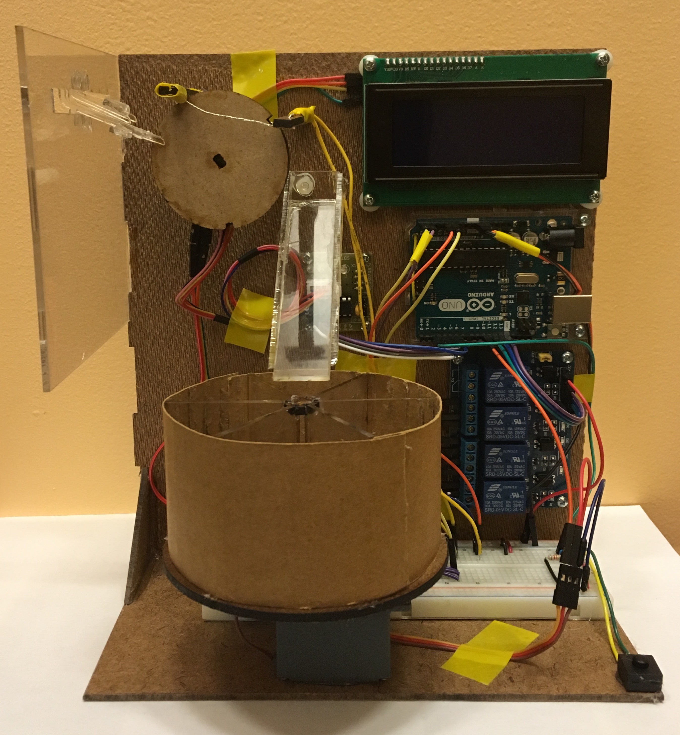
We created the Revolution, a resistor sorting machine that introduces resistors one at a time into a resistor measuring circuit, outputs the measured resistance to an LCD screen, and sorts the resistor into an appropriate slot.
 The Revolution
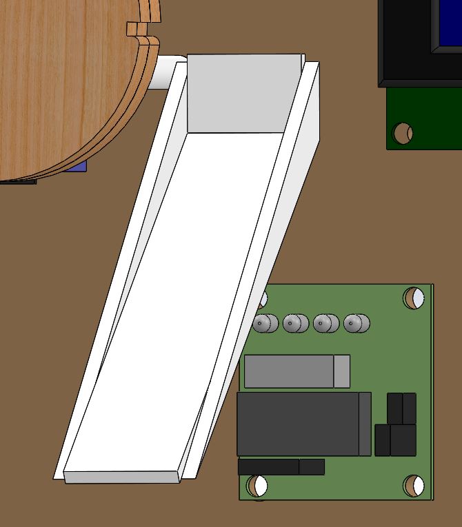
The Revolution in Action
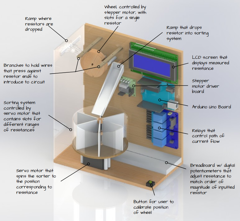
Overall System Diagram
Electrical Component
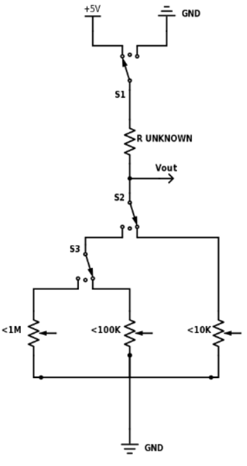
Basic Voltage Divider Circuit to Measure Resistance
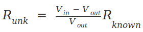
To measure the resistance, we created a voltage divider, with one known resistor value and one unknown. Using an Arduino, we can analyze the voltage reading in between the two resistors and calculate the ratio of resistance between the two resistors. The current passing through the resistors in series, as shown in the diagram below, is the same. That means:
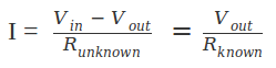
Thus, we can calculate the resistance of the unknown resistor using the equation:
 Voltage divider circuit
The problem with this design is that the voltage we read is based on the ratio between the two resistor values. The arduino can only accurately read voltage up to a certain point, so the further apart the resistor values get the less accurate our reading will be. We resolved this problem using digital potentiometers to adjust the resistance of the known resistor until it is at the same order of magnitude with the unknown resistance.
We used potentiometers with maximum resistance values of 10 kΩ, 100 kΩ, and 1 MΩ and precisions of 39 Ω, 390 Ω, and 3900 Ω respectively. This allowed us to measure any resistances between 100 Ω and 1 MΩ with reasonable accuracy.
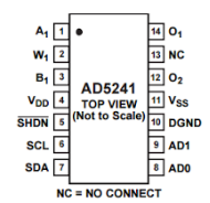
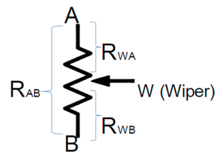
Our first step in learning to use the potentiometers was understanding the purpose of each of the 14 pins on each potentiometer. We used the AD5241 datasheet and online records of projects that used digital potentiometers to annotate and use the pins as shown in the diagram below.
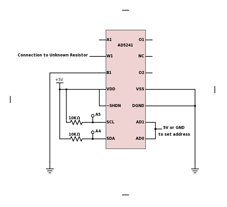
We used an I2C interface to control the potentiometers with an Arduino. This required that we connect the SCL (serial clock input) and SDA (Serial Data Input/Output) pins on each potentiometer to the A5 and A4 analog pins on the Arduino microcontroller respectively. Since we only had one of each of these pins we created different addresses for the potentiometers while they shared the same pins on the microcontroller.
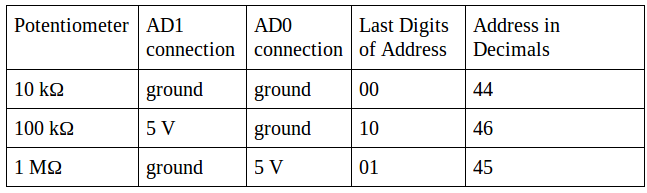
All the potentiometers share a slave address byte of 01011[AD1][AD0], where AD1 and AD0 can be either 1 if connected to 5V, or 0 if connected to ground. The table below explains the AD1 and AD0 connections in each potentiometer and their corresponding addresses.
Once the circuitry was complete, we tested and calibrated each potentiometer by measuring the resistance across W1 (wiper) and B1. This is the resistance of what we refer to as the known resistor in the voltage divider circuit.
Using this process, we were able to get generally close values (±5%) for the test resistors.
Relays
We used relays to make sure that at any given time only one of the potentiometers (with resistance of the desired order of magnitude) was connected to the voltage divider circuit. We used the first relay (labeled S1 in the final circuit schematic) to connect the entire circuit either to power (5V supply) or ground. The other relays help channel the current to the desired digital potentiometer.
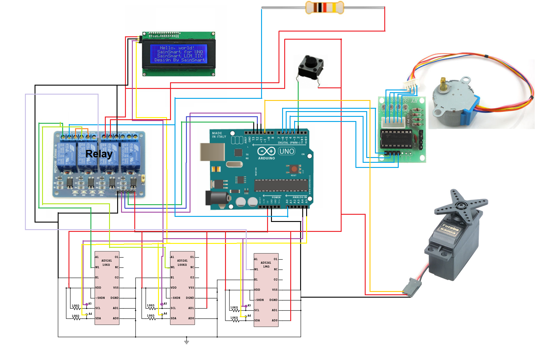
Final Circuit Schematic: Integrating Digital Potentiometers and Relays
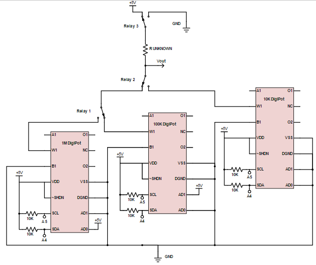
We switch the states of the relays (on or off) to control which potentiometer is Rknown at a given time. For example, in the setup depicted in the schematic, when relays 1 and 2 are off, they make connections such that Rknown is the 100k potentiometer.
We calibrated our digital potentiometers and created equations to calculate their resistances as accurately as possible. We did this by setting the digital potentiometer to a number of values, and recording the actual resistance of the digital potentiometer at that value with a Ohmmeter, and then creating a “best fit” calibration curve from those points. This was because we noticed that the equations provided in the data sheet were giving us somewhat inaccurate results.
This allows us to dynamically alter the resistance we are testing against in order to get the most accurate results. By using our relay system with the three digital potentiometers, we are able to accurately find the resistance of a very wide range of resistors (100Ω to 1MΩ). We tested our system with a wide range of resistors and found that we could accurately find the resistance of all of them, with a maximum error of 5%* of the resistance value.
*made up number, but likely accurate
Mechanical Component
A Full CAD of the project along with its assemblies may be found here.
Feeder Ramp
We decided that the best way to get the resistors from the user to the circuit that measures them was to create some sort of feeder that the user could drop as many resistors on it as they wanted and just let the machine work through the que. To achieve this, we tested 4 different ramp designs before settling on the one we have now. The way this ramp was intended to work is as follows:
The user inserts the wide plastic portion of the resistor into the middle of the ramp with the leads of the resistors straightened and coming out of the slits on the sides of the ramp.
The ramp then controls the sliding of the resistor by keeping it centered until it is about to enter the notched wheel. At this point, the top guiding portion falls away and allows the resistor to free slide for the last half inch or so. At the end of the slide, the bottom widens and hugs the notched wheel and gravity pulls the resistor down to where the wheel and the ramp meet.
This was by far the most difficult mechanical aspect of this project. While the feeder ramp generally works up until the point where the top guide goes away, the resistors do not reliably fall into the crevice between the notched wheel and the ramp. This is likely a combination of physical fabrication (e.g. extra hot glue may be guiding the resistors out of the correct orientation) as well as potentially overcomplicated design. There is likely a much simpler way of doing this particular aspect of our project that would be more effective.
Notched Wheel
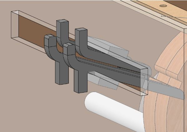
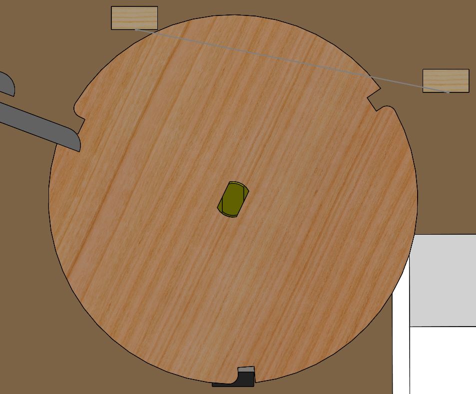
After the resistor falls to the bottom of the feeder ramp, it is picked up by a wheel with three notches. These notches are spaced such that as the wheel continuously turns clockwise, a resistor is either being picked up, tested against the circuit, or dropped onto the sorting ramp. When the notched wheel picks up the resistor, it is in the position below. This position allows a single resistor to roll into the precisely sized notch and be picked up.
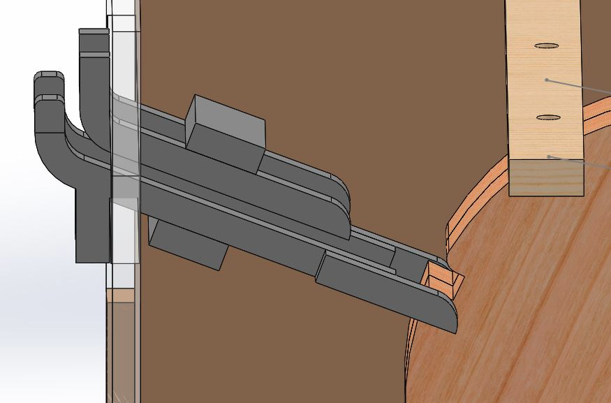
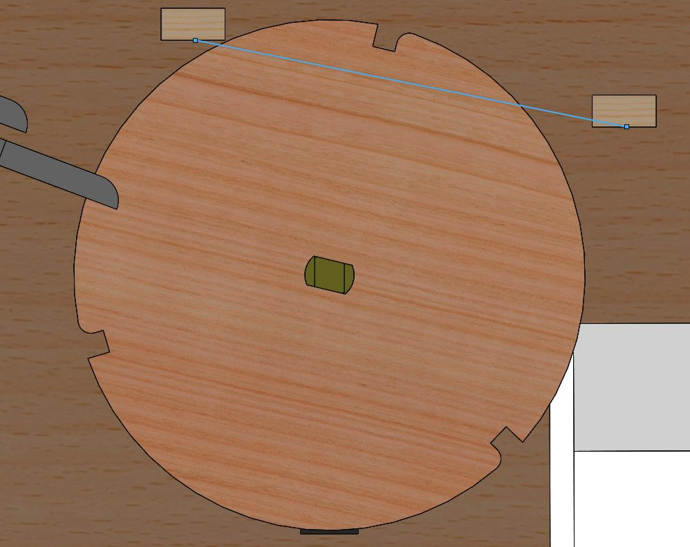
In the testing phase of the feeder wheel, the wide part of the resistor is seated solidly in the notch with the leads sticking out over the sides. These leads are pushed up and into exposed wires, causing the resistor to complete the circuit and allowing the circuit to test the resistor. This position is shown below with the positioning of the wires shown in blue. Note that the notch is approximately a tenth of an inch above the wires. This ensures that even if the resistor went into the feeder wheel slightly bent, its leads will make a secure connection with the circuit.

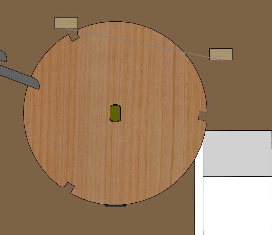
Finally, the notched wheel continues to turn after the resistance has been determined until the resistor slips out of the notch and falls onto the sorting ramp. The position of the wheel at this point is shown below:
Of all of the pieces of our mechanical system, the wheel worked most effectively. Its design was based on the conceptual design of a toothpick dispenser; it could have many resistors pressing against it at once, but will only take one with every notch.
Sorting System
The final mechanical portion of our project is the sorting system. After the notched wheel drops the resistor, it falls onto a ramp.
This ramp is wide enough that it is able to catch the resistor reliably when it falls from the notched wheel and serves the purpose of reorienting the resistor so it can fall more or less vertically into the actual sorting vessel.
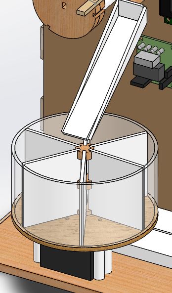
The vessel itself has 6 compartments, which split sorted resistors up into 6 groups:
- Segment 1: <1K
- Segment 2: 1K-5K
- Segment 2: 1K-5K
- Segment 2: 1K-5K
- Segment 3: 5K-10K
- Segment 4: 10K-50K
- Segment 5: 50K-100K
- Segment 6: 100K-1M
Software/Firmware Component
The software components of the product are all compiled into a main program in Arduino C that coordinates the LCD screen, stepper motor for the wheel, servo motor for the sorter, and reading the resistances using the relays and digital potentiometers. Luckily, all of these processes run on one schedule. The main loop tests the resistance (using the digital potentiometers), prints it to the LCD, moves the sorter wheel, then moves the main wheel so that the next notch is against the wires up top.
We separated as much as we could into different methods. We have methods to step the stepper motor, to calibrate the wheel using user input, and a method to find the most accurate resistance prediction, as well as the corresponding helper methods to set the relay configuration, write commands to the digital potentiometers, and read the current resistance guess. Because of our generous use of methods, it's easy to swap out different functions--for example, it would be easy to replace the digital potentiometers with resistors, and it would be easy to come up with a new calibration method and replace the old one.
To control the LCD, we used the LiquidCrystal library. We had to replace the LiquidCrystal library that comes with Arduino, with the latest version. We also had to find the I2C address of our LCD, using an I2C scanner. To interact with the lcd, we started, in the setup() function, with lcd.begin(). After that, we used three main methods to interact with the LCD: clear(), to clear the screen; setCursor(), to set the column and row to begin displaying characters; and print(), to draw characters onto the screen. We use the LCD throughout the program, to prompt the user for calibration, and to display the resistance of resistors.
For the Stepper, we were originally going to use the Stepper library for Arduino; however, for some reason, our stepper refuses to run backwards, and in a previous iteration of our design, our stepper had to move backwards. Thus, we adapted some code from this Instructable to manually program its movement, and left it in after we redesigned the system such that the stepper would be compatible with the Stepper library. The basic idea is that there are 8 steps that correspond with certain stepper orientations. by stepping through those steps, the stepper will slowly turn. Each step has a certain configuration of pins. Our code iterates through the 8 steps, skipping every other one to make the wheel turn faster. This is reflected in the method singleStep().
Because the stepper keeps track of relative location, and not absolute, and we want to keep track of when the resistor will be touching the top leads the measurer, we designed a calibration system to run at the beginning, contained in the calibrate() method. Basically, the wheel begins turning, and the LCD prompts the user to press the button when a notch is aligned with the ramp. Then the wheel moves the correct amount of steps such that the notch is against the wires. That way, we are able to time when to test the resistance and move the sorter.
To test the resistance, we have a combination of relays and digital potentiometers. The circuit for the digital potentiometers are laid out above. The code to find the resistance is encompassed by calling bestResistance(). It turns on the third relay (which allows current to pass through the circuit), then iterates through the three digital potentiometers. The digital potentiometers communicate over I2C and each have their own addresses. The potentiometers change their resistance based on the value of a byte (0-255) being sent over I2C. The resistance that corresponds to that byte value can be calculated by a simple linear equation for the 10K and 100K potentiometers, and by a cubic for the 1M potentiometer. All of these equations, addresses, and communications are handled in the writeDigiPotResistance() method. For each potentiometer, we first iterate through all the values in a byte by 20s, then find the best value of those (which is the value at which the ratio (5V / vout) is nearly 1/2, vout being the voltage in the middle that we are measuring), and test the values that are (+/-) 20, by 10s. Then we narrow it down further, checking each value that is (+/-) 10 of the best resistance found so far. It then prints out the resistance and returns it.
For sorting, we use the Servo library, and came up with 6 different categories to sort the resistors. We then wrote the servo to go to the angle that corresponds witht that section of the vessel. This is contained in the setSorterWHeelPos() method.
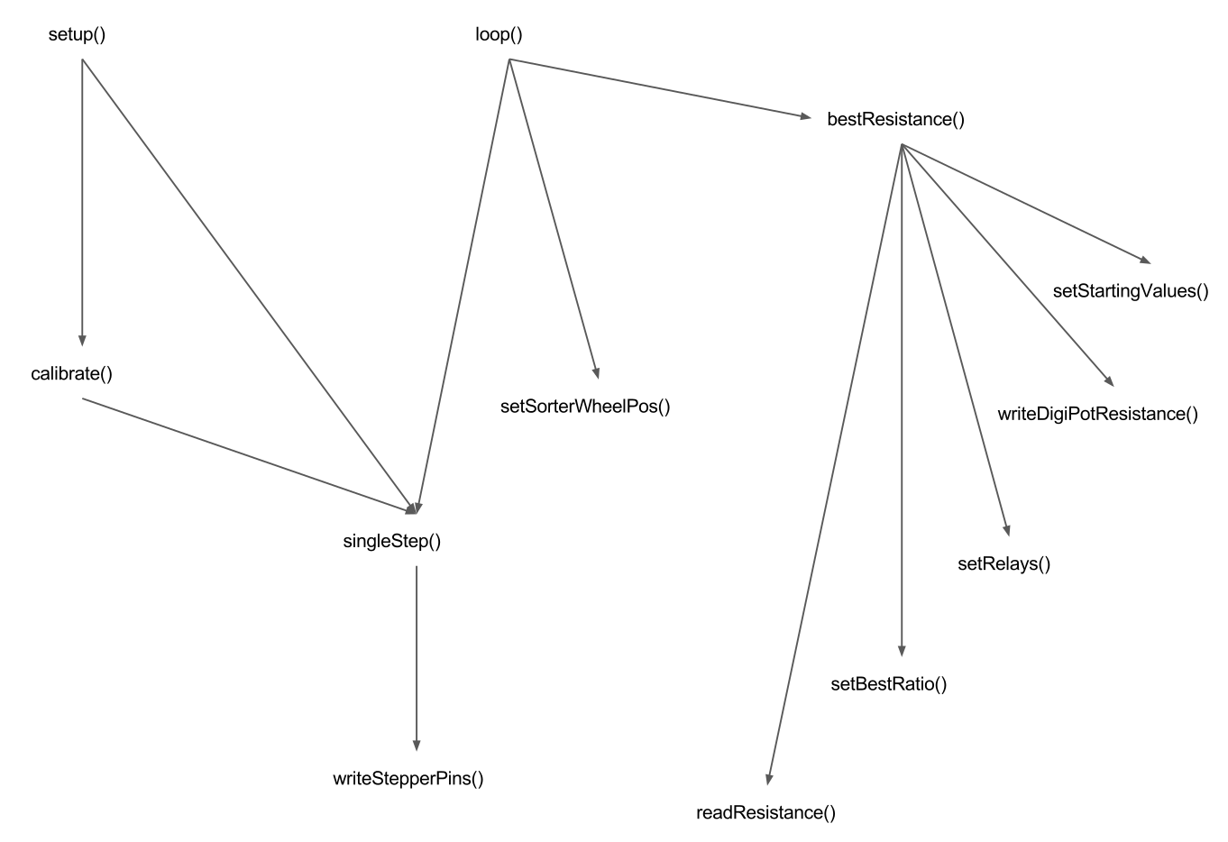
Organization of Method Calls in ResistanceTester
The other programs in the Github repository were for testing and building the different subsystems.