Software Systems
We want the engine to trigger the solenoids based on the angular position of the crankshaft and cool itself down with fans based on thermocouple readings, and to be remotely controllable via microcontroller. Check out our code on git here!
Sprint 1
We worked theoretical control code for a single-solenoid engine. The solenoid needs to be active when the crankshaft is in the right position and inactive for the rest of its rotation, so in our control loop we constantly read the encoder input so we know where the crankshaft is at all times. When necessary, we set the voltage high to trigger the solenoid. We also included RPM-limiting into the control loop to ensure it wouldn't run too fast.
Sprint 2
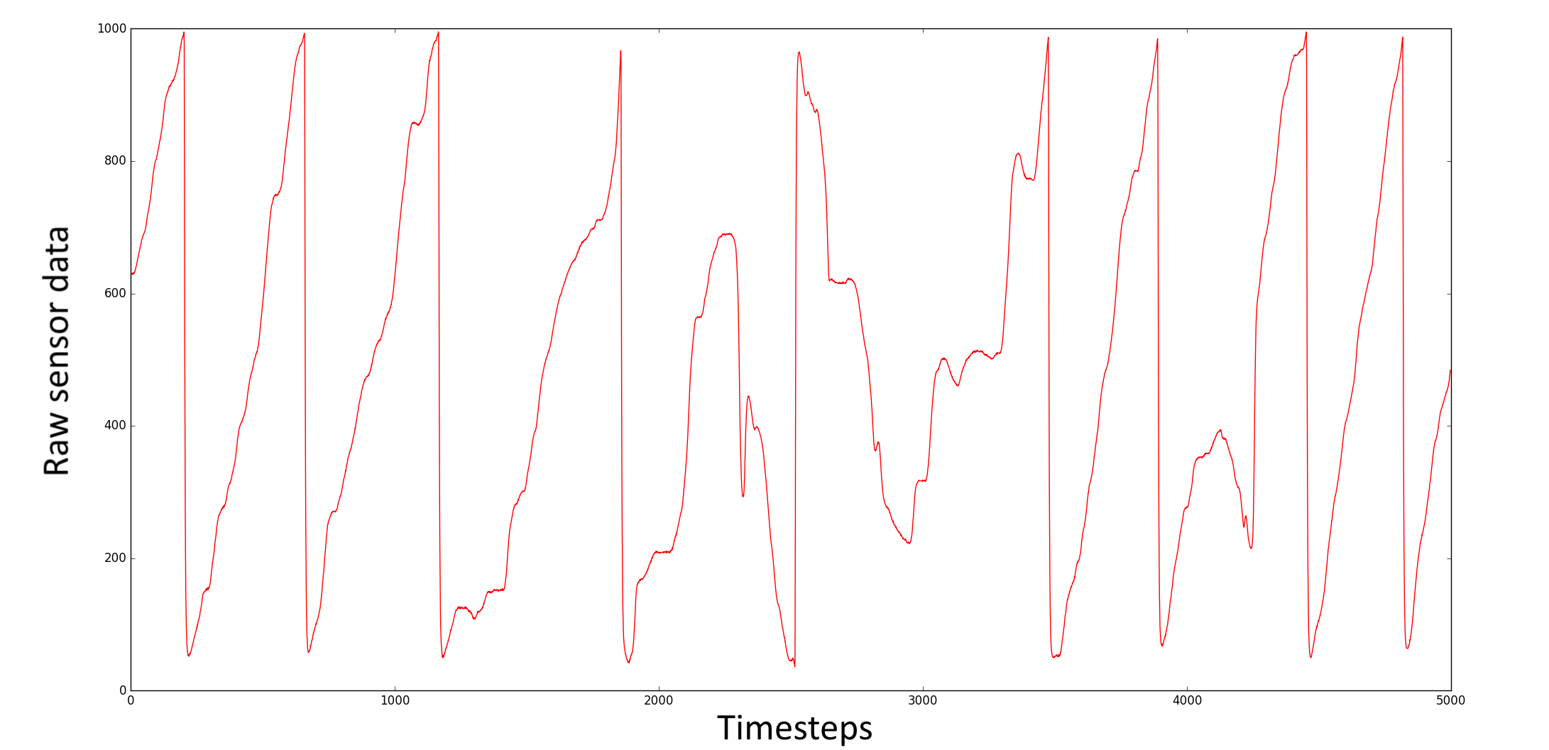
We got our hands on the rotary encoders and tested them out by logging their readings to a text file via pyserial. In addition, we wrote proof-of-concept scripts on Arduino and Pyserial for real-time communication.
Near the end of the sprint we got the single-solenoid engine operational - the control code worked just fine!

Sprint 3
We implemented a HTML/Javascript -> Python flask/flask-socketio -> Python pyserial -> Arduino Serial pipeline for users to edit engine parameters in real time via a web UI.
The Flask and Flask-socketio libraries allow python to communicate with Javascript's Socket-IO library. This allows us to receive asynchronous data updates (without a loop checking for events) from our webpage. Once we have those, we use Pyserial to send the data we collect to our Arduino microcontroller's serial monitor, where the message is parsed and system operating variables changed. We could've achieved real time control by typing commands directly into pyserial, but decided to make the system more user-friendly by embedding it on a locally-hosted webpage.
Sprint 4
Everything starts to come together! We connected the solenoids, MOSFETs and Arduino. We wanted to be able to match engine RPM with a 'desired_rpm' variable which can be changed via Sprint 3's real-time control, and decided to use a PI controller. Two-thirds of PID (proportional–integral–derivative), our controller outputs a value between 0 and 1 depending on 1) our current proportional error (the percentage difference between our current RPM and desired RPM) speaking and 2) integrated error (if the current output is not strong enough, the integral term will accumulate over time, causing a stronger output). We decided not to include the derivative error term, which takes into account how quickly the error is changing, since it makes the system more sensitive to noise and our rotary encoder does have a small amount of deviation between values.
Once we have our output term (between 0 and 1), we use analogWrite() from one of the Arduino's PWM (pulse-width modulation)-capable pins to send a signal of corresponding strength