Mechanical Systems
How we're turning magnetically actuated linear motion into rotational motion.
The design of our engine is heavily influenced by the design of a 4 stroke inline 6 internal combustion engine, like those found in several BMW or Mercedes-Benz models. The final engine features pairs of cylinders, at positions mirrored across the crankshaft's middle point firing simultaneously to ensure balanced load along the shaft. This page will follow the progress of our design through the 4 sprints, and 3 main iterations that it takes.
Sprint 1: Genesis
Cardboard, tape, and Solenoids.
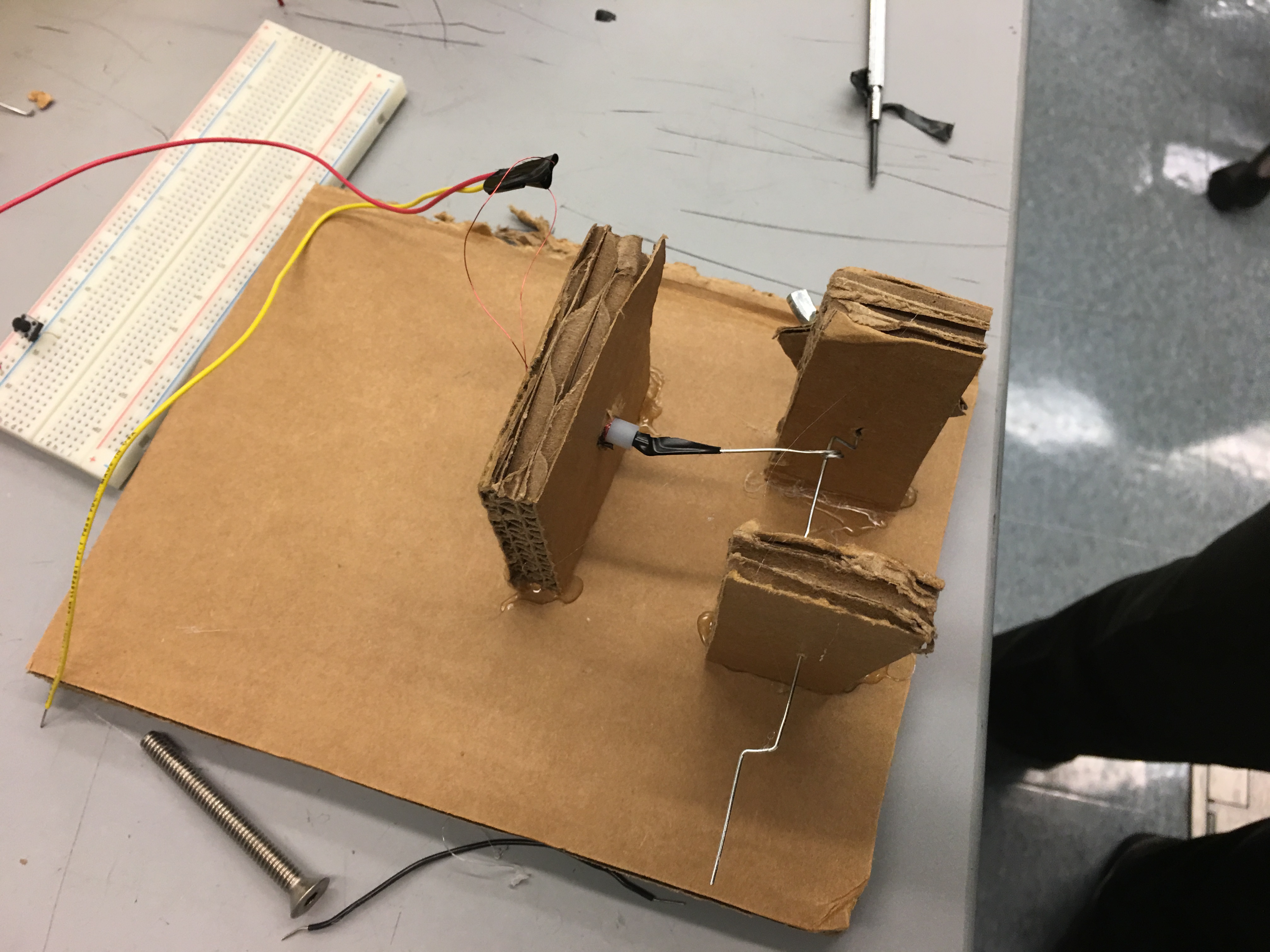
In our first sprint, we threw together the simplest interpretation of what a Solenoid engine could be. We wrapped some 24 gauge magnet wire we found around a plastic tube we had lying around, and assembled a rudeimentary crank out of steel wire. We turned a small steel rod into our piston, and taped that to a homemade bearing on the crank. We then powered the system by holding a connection to a power supply, and bending some wire attached to the crank so that it would make contact just after the piston passed bottom-dead-center (BDC). A rotating mass made of wing nuts glued to some cardboard allowed the crank to continue spinning when not powered.
Obviously this first system was rudimentary to say the least, and as you can see from the video, doesn't work particularly well. However, what it did do was validate our entire solenoid engine concept, and give us a basic idea of what we should do moving forwards.
Directly foloowing the completion of our first iteration, we began work on the second iteration of our solenoid engine, which was to be a more polished single cylinder engine with power modulation done digitally. This second intertion would also serve to help us learn about solenoid design as a whole, and help us nail down a wire gauge for the final product. The image above shows the rotating mass and connecting rods for engine v2.
Sprint 2: Acrylic and Polish
Designing and manufacturing a more polished single cylinder engine
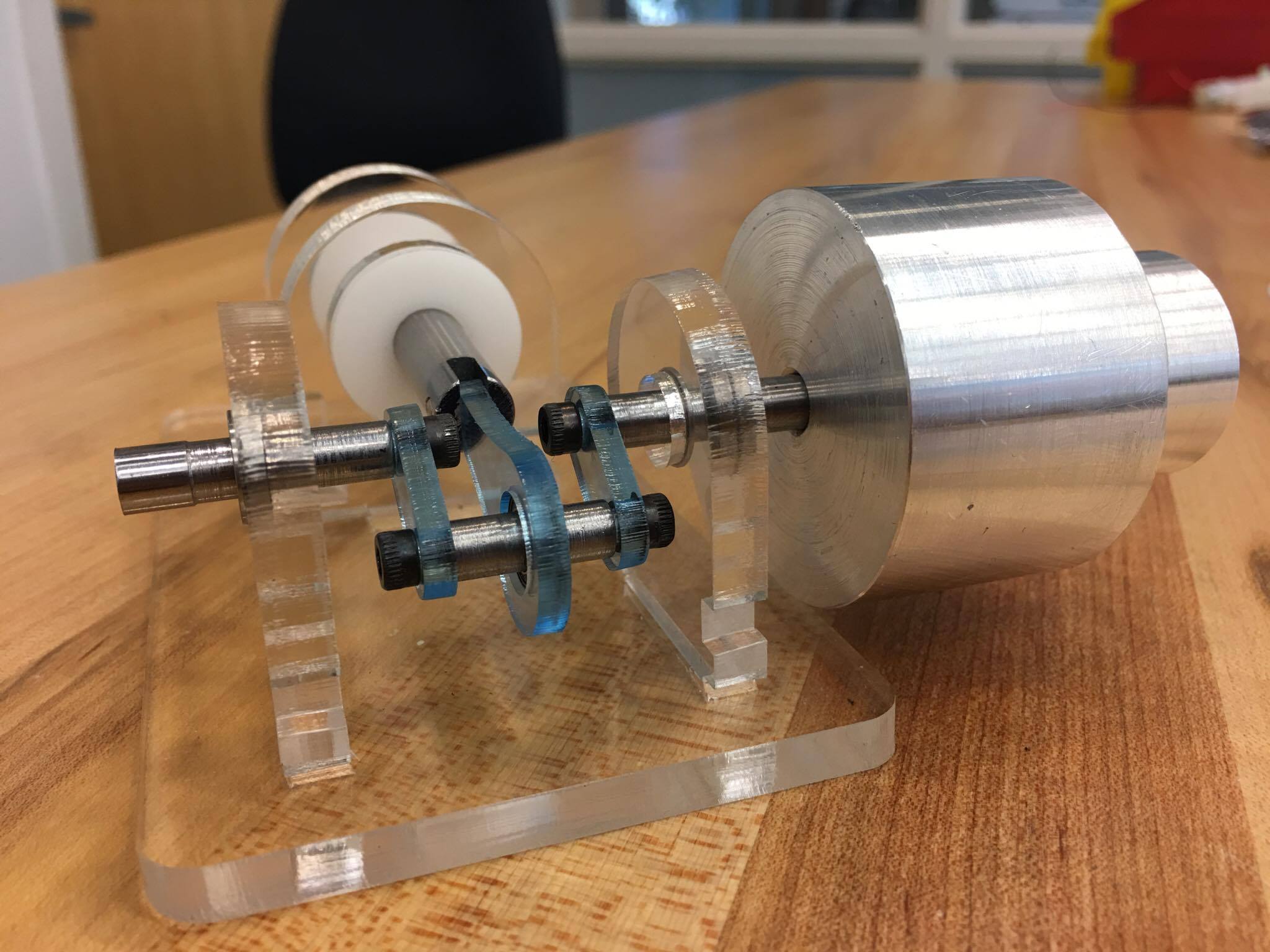
The above image shows the mechanical progress made between iteration 1 and iteration 2 of our solenoid engine. The layour remains much the same, with a single solenoid. However, much has been done in the realms of making a mechanically sound and polished system. All components are either CnC aluminium, ferric steel, acrylic, or delrin. All rotating components are mounted in bearings to reduce rotational resistance. The fit between the solenoid and the ferric rod is tighter to ensure no lateral slop, and to reduce the empty space, increasing solenoid efficiency.
The above video shows our updated proof of concept in action, including in gratuitous slow motion. As you can see, the added degrees of mechanical polish have greatly increased the effectiveness of the engine. At the same time, we began to optimise solenoid design around this time, working with different gauges of wire to determine which would be optimal for this iteration, as well as the final iteration. This iteration is also the first time we 'used our digital control method, with a magnet on our output shaft, and our rotary position sensor on the perpendicular breadboard providing crank position information for our circuit to interpret and use to send power to the solenoid.
Sprint 3: The final project takes shape
Sprint 3 was an interesting time, full of setbacks and machining. Coming into sprint 3, we decided to take the momentum we had built and move straight towards our final goal, without building an MVP to begin with.
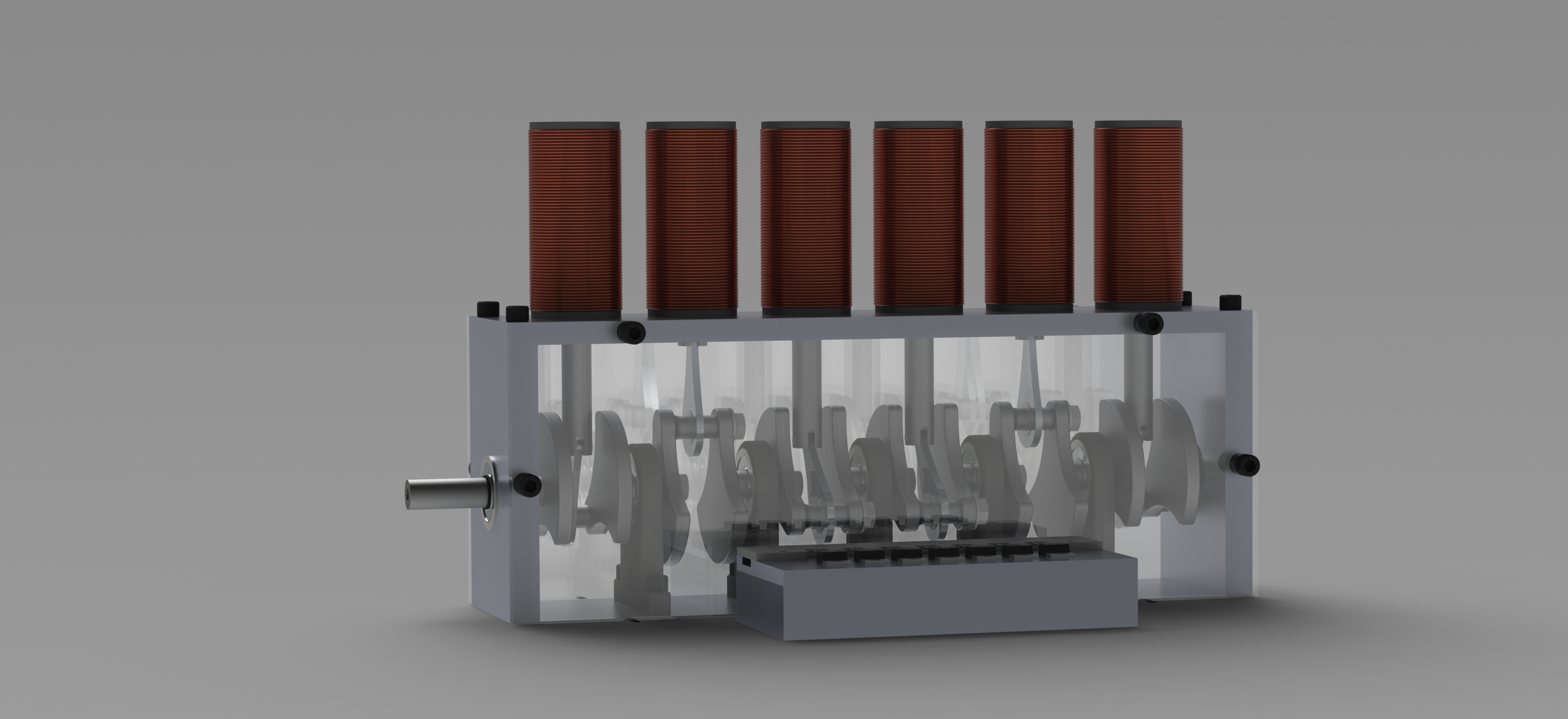
So we skipped over all of the preamble, and decided to work towards our final project, a render of which is above.
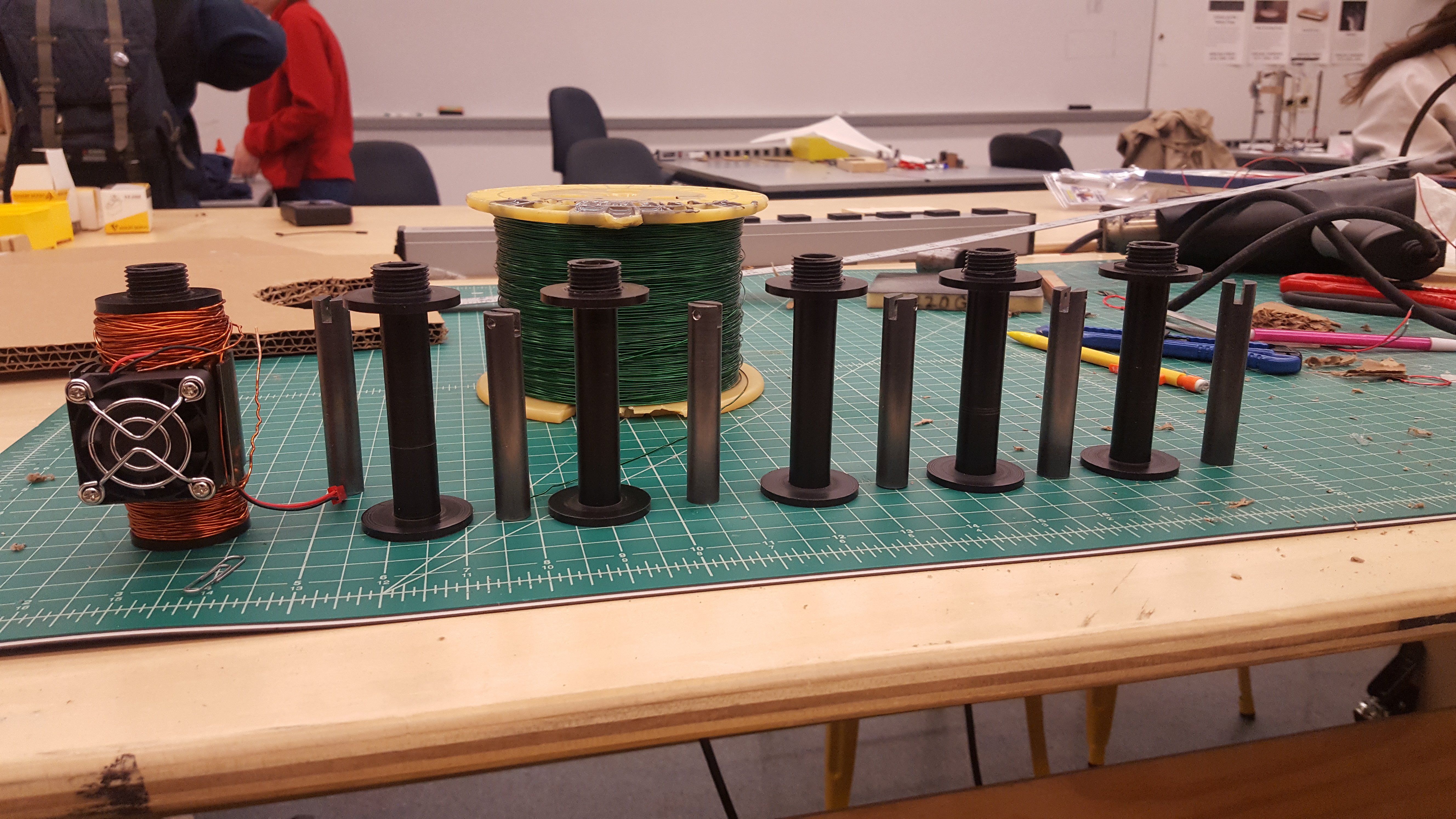
We finalised the dimensions of our solenoids, and turned them out of black delrin.
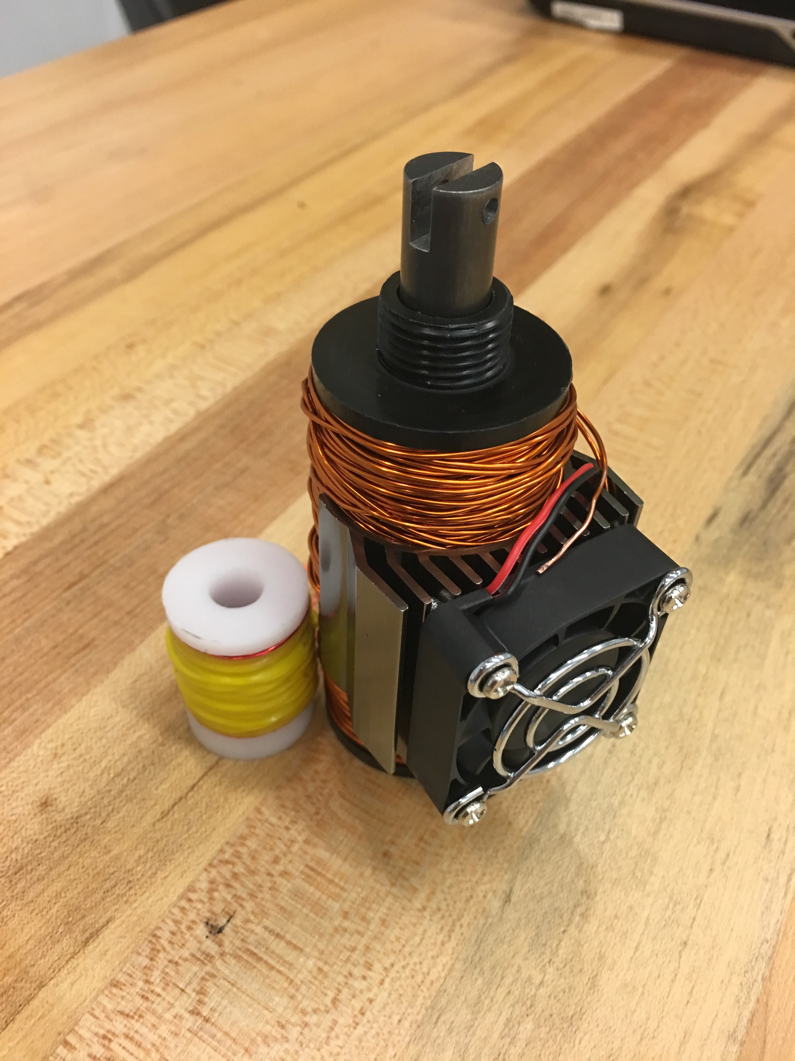
Here is a comparison of one of our final solenoids, next to the solenoid from our second iteration of the single solenoid engine. It should be noted that each solenoid has over a pound of copper on it.

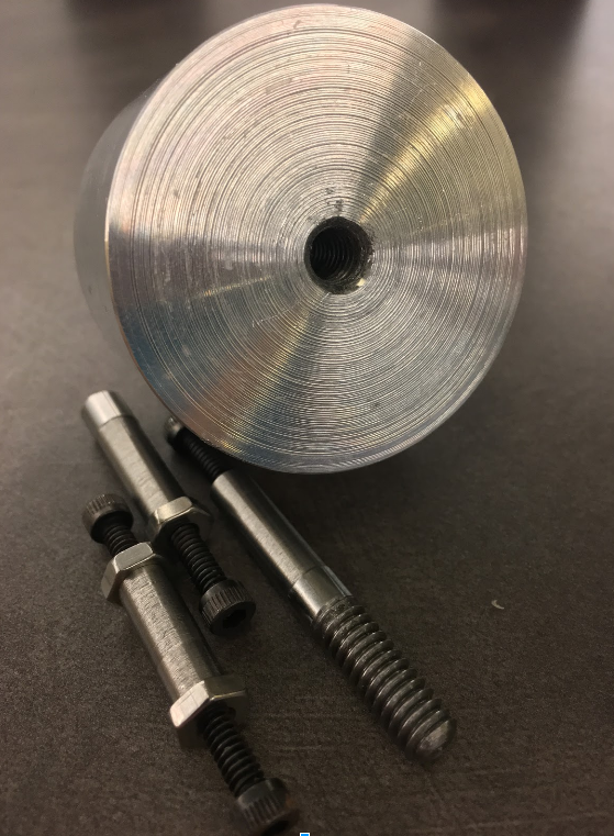
When machining our pistons, we bought wear-resistant steel, making machining them a very difficult proposition. Thus, we annealed them, as shown above, to make them soft enough to machine.
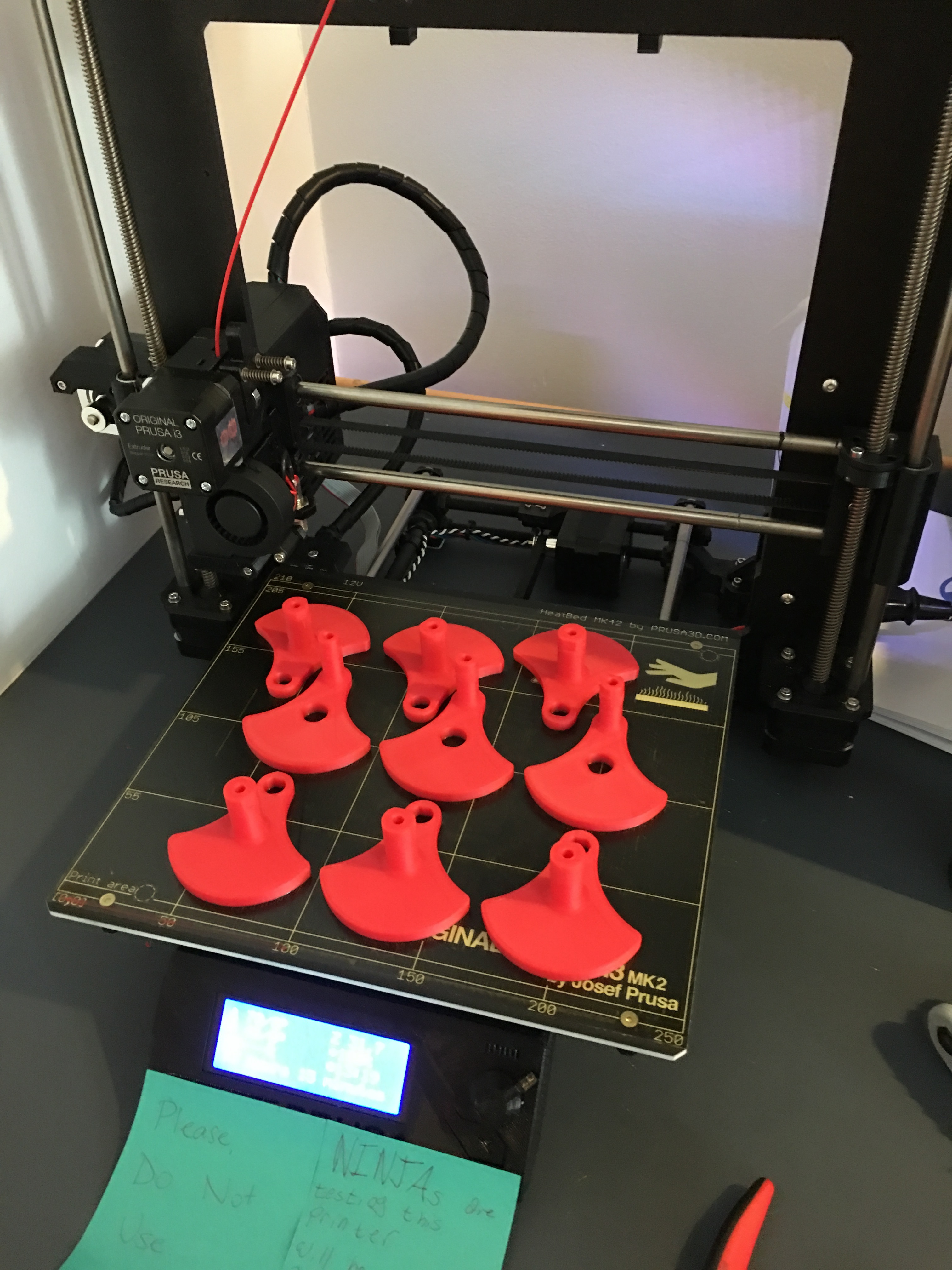
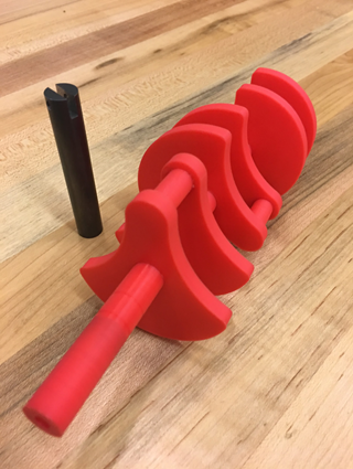
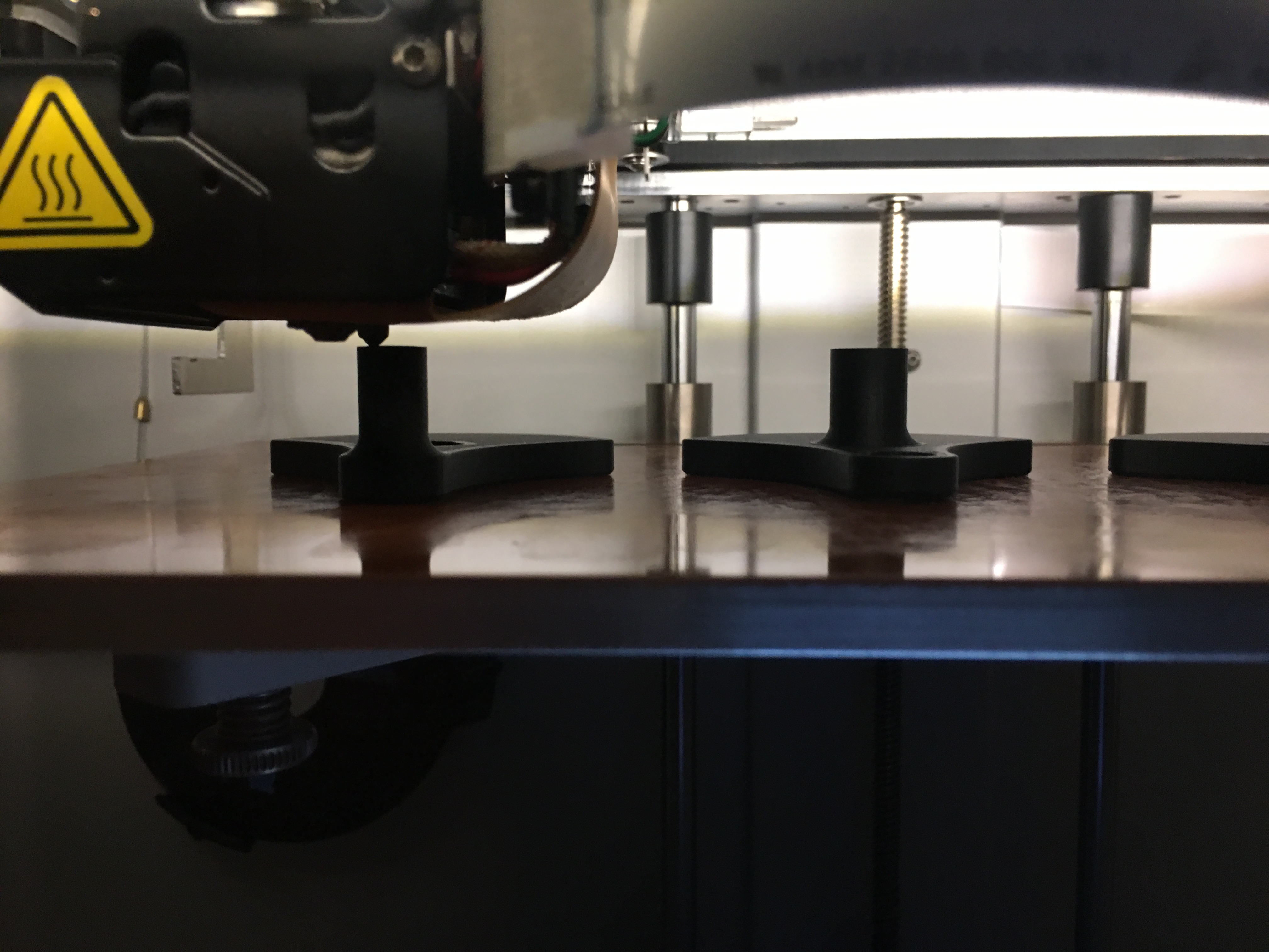
As our final act in sprint 3, we printed a test crankshaft to make sure our tolerances and fit were good enough for a final product. Our test crank was 1/2 the length of our final, and printed out of ABS on a Prusa i3 printer. Our final crank will be made out of Onyx (chopper carbon fiber) filament on a Markforged printer.
Sprint 4: The home stretch
Sprint 4 is when everything comes together. The last of our machining was completed in the second week of December.
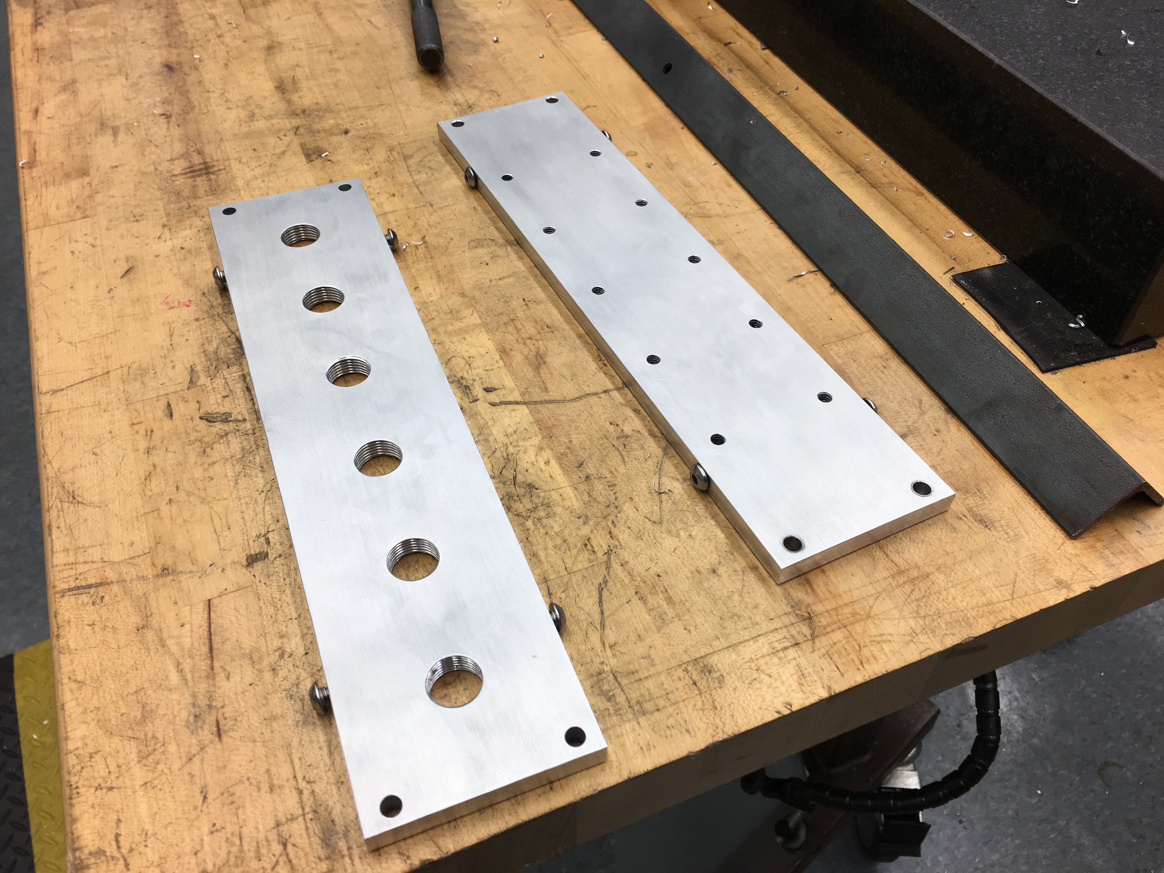
Hunter CnC milled the top, bottom, and end plates for the solenoid engine, after we had taken them down to size.
We then printed our crankshaft and counterweights on our markforged.
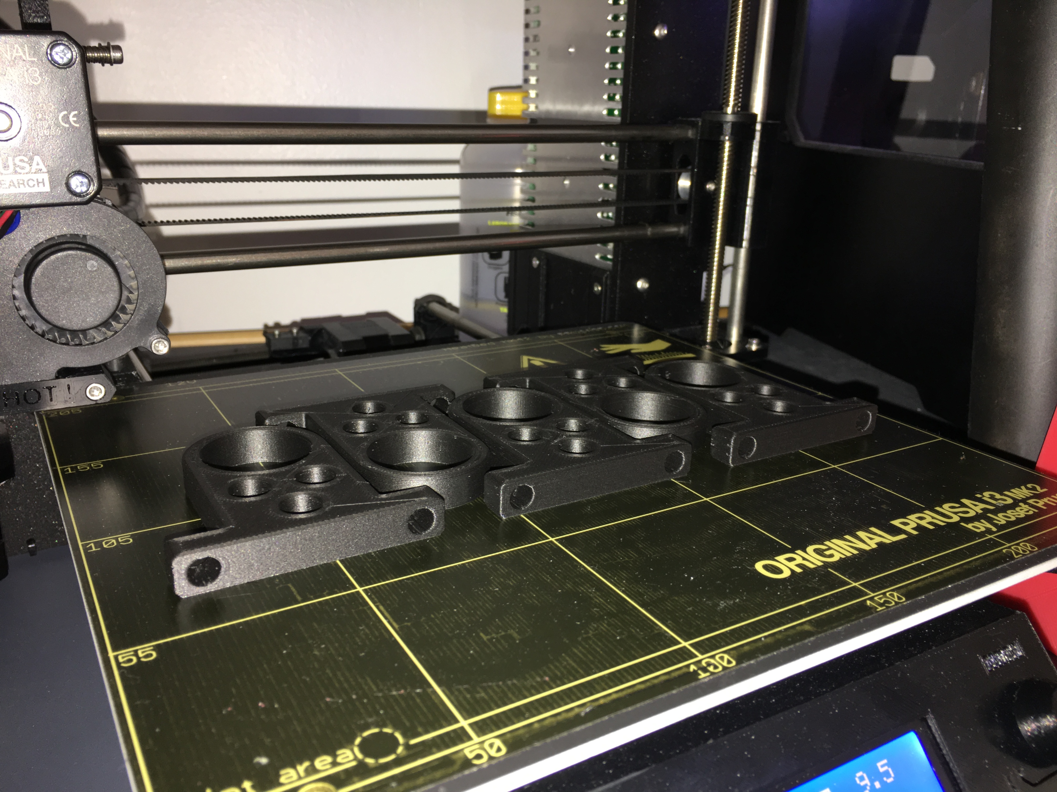
We also printed a set of bearings blocks on the Prusa. These bearings blocks support the crank shaft between each piston, ensuring that there is no latitudinal force along the shaft.
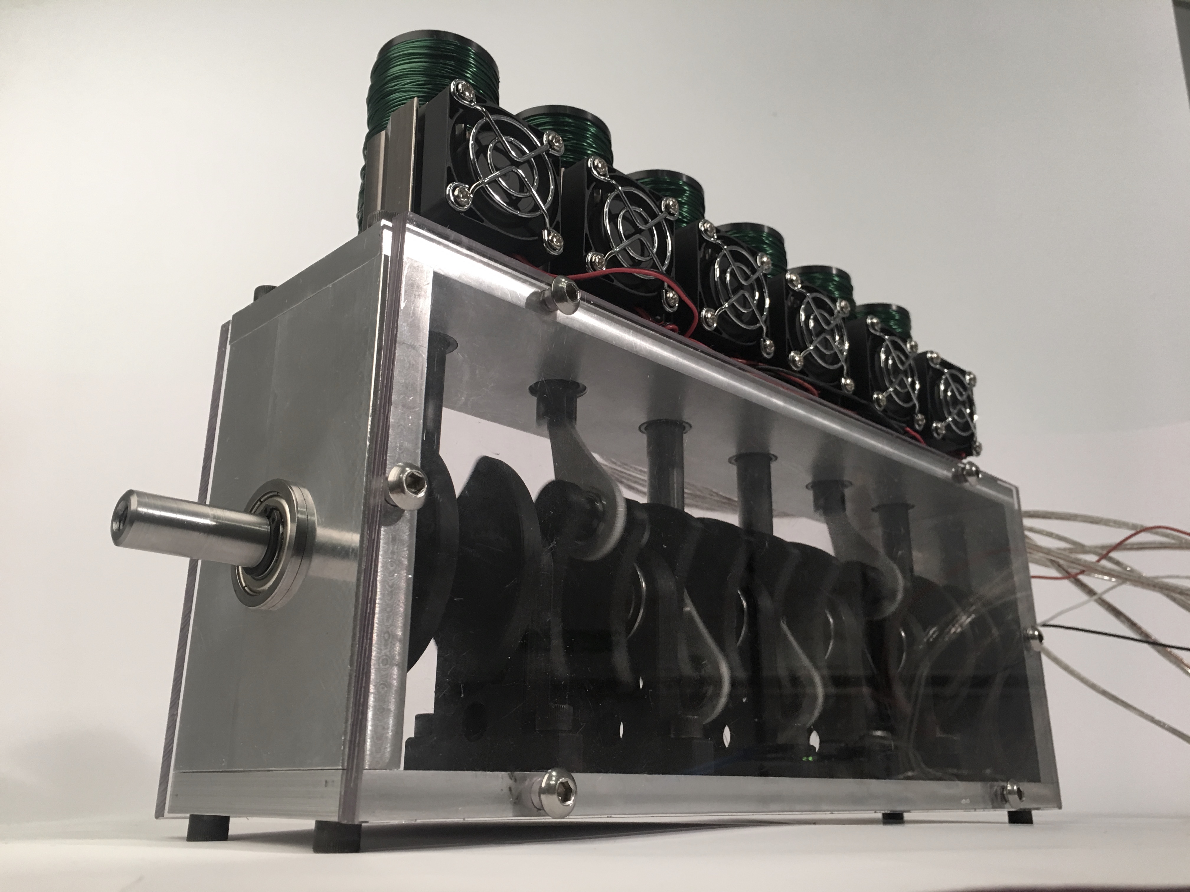
Finally, we arrive at our completed mechanical system. As you can see, the Solenoid pots are threaded, and fit into the top plate. The crank has been assembled, and is supported at each end, and between each piston using bearing blocks. The pistons are on their arms, and seated within their pistons, and everything is held together. Our polycarbonate siding is installed to protect our internals from the outside, and to protect viewers from our internals, should something fail.