Electrical Systems
Controlling the magic that is electricity
From regulating current flow to allowing our software to interface with the real world, electrical systems play a huge part in our sytems. After all, solenoids need electricity to produce an electromagnetic force. Our electrical system consists of the wiring that allows us to control current flow with an Arduino and the various sensors that inform us of the state of our engine.
Sprint 1: MOSFETs
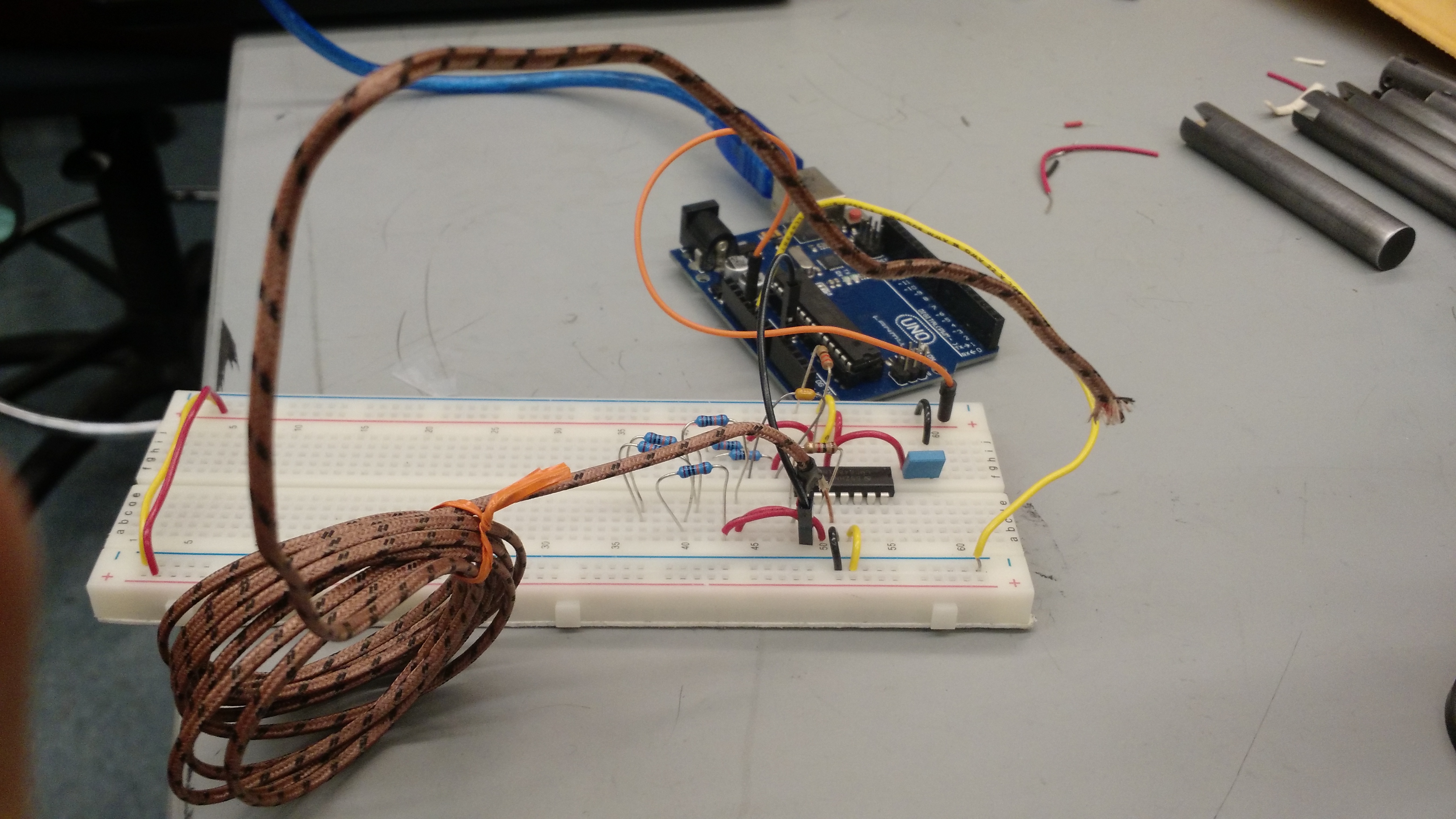
For our first sprint, we investigated various rotary and temperature sensors, and decided to work with a small rotary encoder chip (AS5134 from AMS) as well as thermocouples. While waiting to acquire the sensors, we constructed a proof-of-concept circuit with a MOSFET that turned an LED on and off.
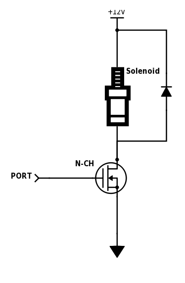
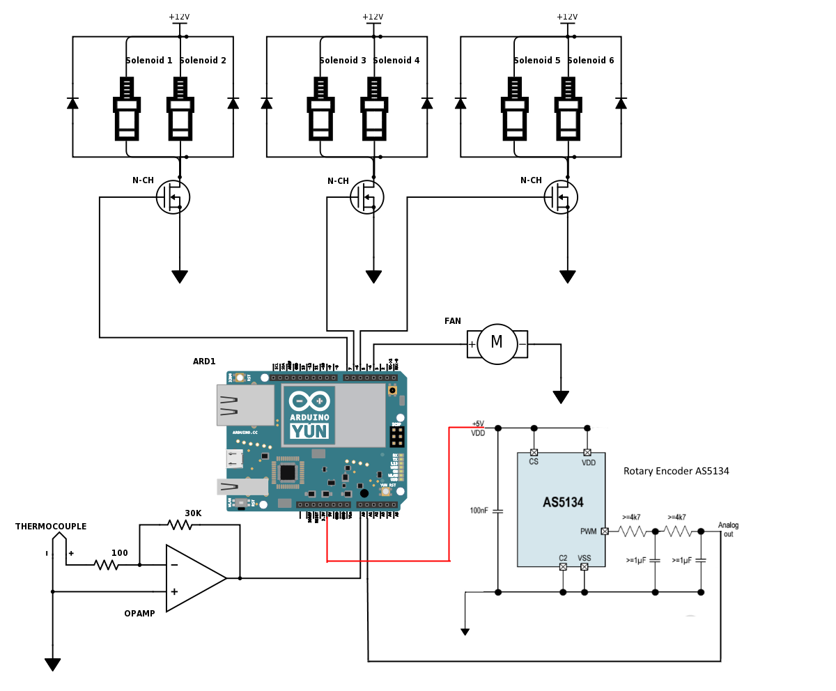
A MOSFET is a transistor that allows us to work with high voltage - our Arduino microcontrollers can only generate 5V, but that's enough to turn a transistor on (allowing current to pass through) or off (no current can pass), allowing us to draw a lot more power than an Arduino can provide. Say, 24V and 3 amps to run through a solenoid.
Our MOSFETs were connected to a test LED circuit, with an external power source connected to run the LED (our testing replacement for a solenoid). When the Arduino sent a signal to the MOSFET, it completed the circuit to turn the LED on, otherwise there would be nothing flowing through the LED.
Once we knew the MOSFET was functional, we hooked a solenoid up to the circuit and gave it a test too!
Sprint 2: Getting Some Rotations
Our rotary encoders arrived from Austria! After wiring them into a circuit by following the sensor's datasheet, we were able to detect magnetic fields. These rotary encoders detect the orientation of a magnet by measuring the Hall Effect across their internal components.
We calibrated them to the positions of a magnet attached to our engine's shaft, and created a map of values for rotational positions of the shaft.
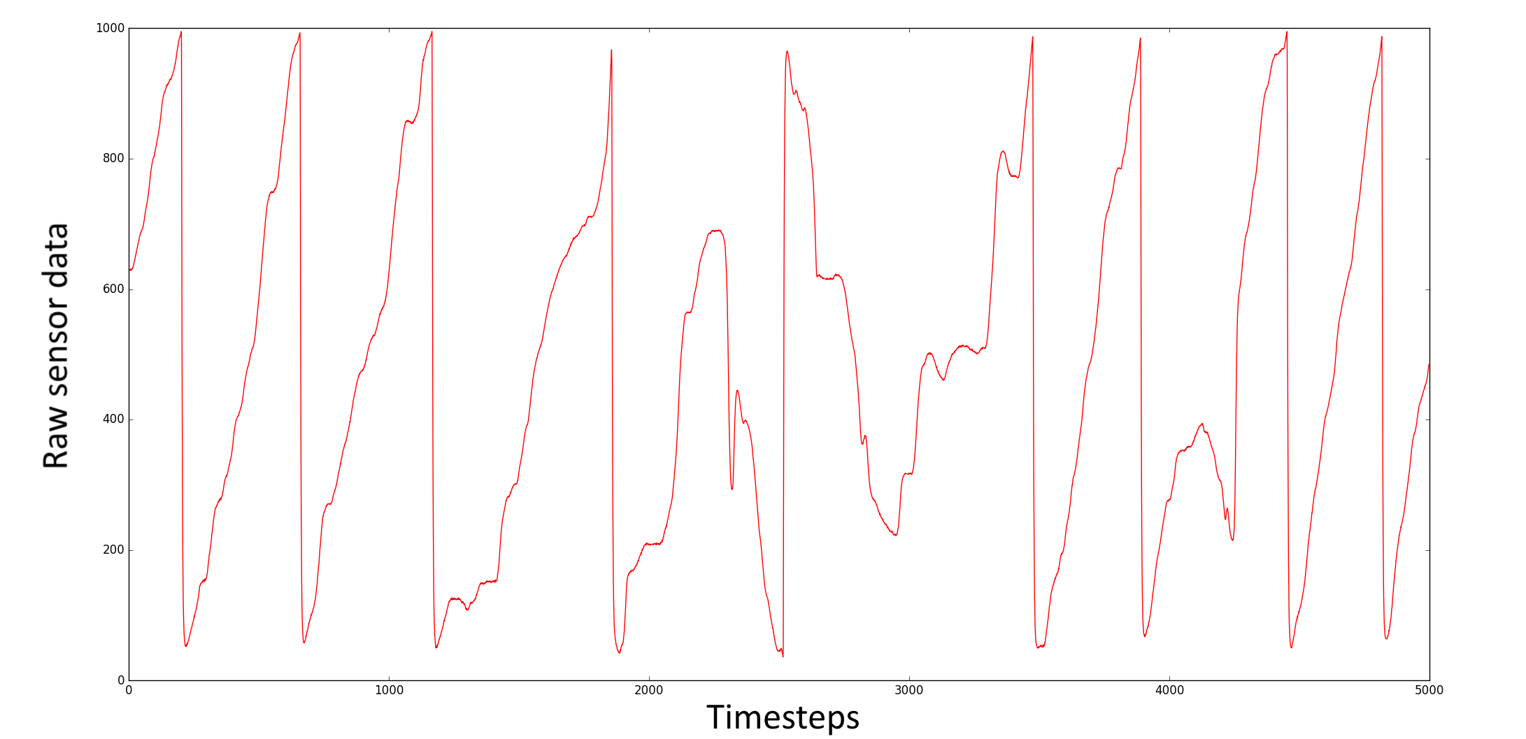
After calibration, we could use the encoders to control the MOSFET connected to our solenoid, activating it to power our single-solenoid system when the shaft had rotated into a proper range for the piston to be pulled.
Sprint 3: Getting Hot
We started work on temperature sensing and further investigation of MOSFET control. We also fried our rotary encoder during testing, so replacement chips were acquired and wired up.
Solenoids generate a lot of heat and back-EMF, so we needed heatsinks and fans to keep them cool, and flyback diodes to prevent the back-EMF from frying anything important. As such, we wired up a thermocouple circuit to measure system temperature and got a bunch of diodes to integrate with our MOSFETs.
The thermocouple generates a small amount of voltage due to temperature changes, so we ran its output voltage through an opamp to obtain a usable value for our software. We then sampled several temperatures with the thermocouples to create a map from thermocouple output to actual temperature, preparing it for integration with our engine.
Sprint 4: RIP
Everything starts to come together! We connected the solenoids, MOSFETs and Arduino, then crossed our fingers and turned on the power.
Unfortunately finger-crossing wasn't quite enough for us, and most of our MOSFET's got burnt out. As it turns out, the flange on the MOSFETs (the tab on the top of the MOSFET) is connected to the drain pin of the MOSFETs and since we had all of them mounted on an aluminum block, most got short-circuited and were rendered useless.
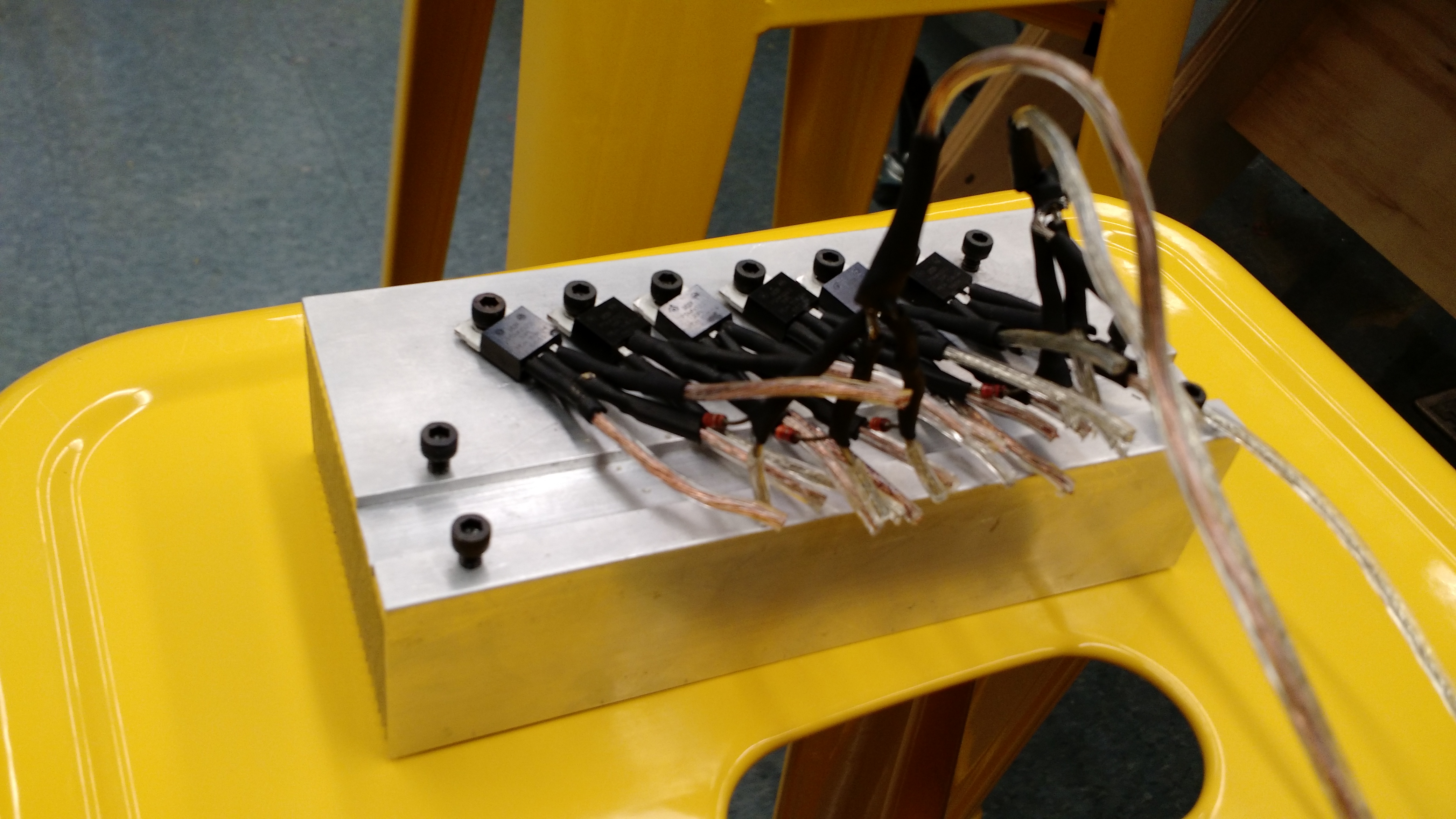
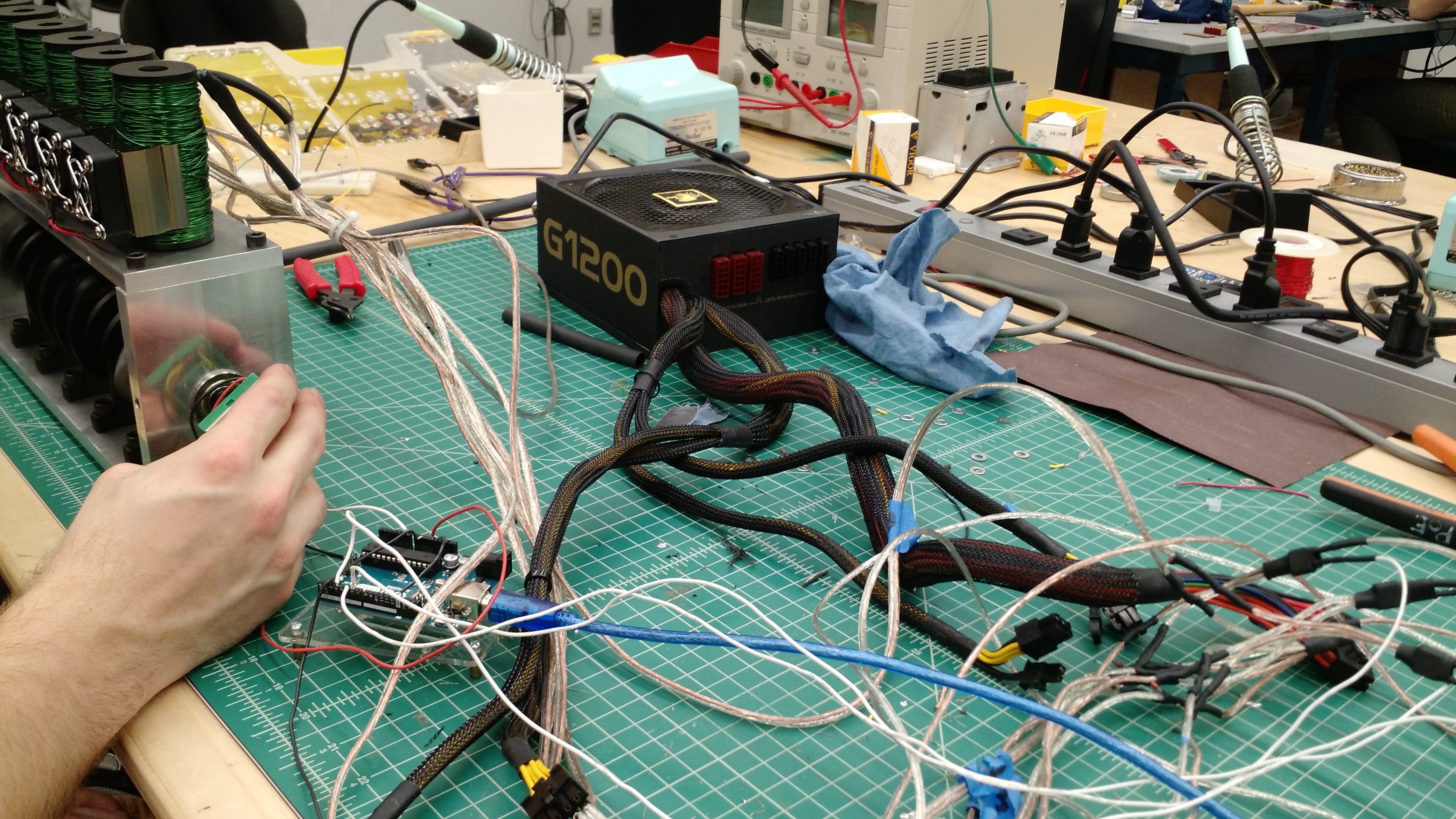
Each solenoid drew about 8 amps at 12V, with the MOSFETs remaining at room temperature and the solenoids heating up only slightly over several minutes of running.