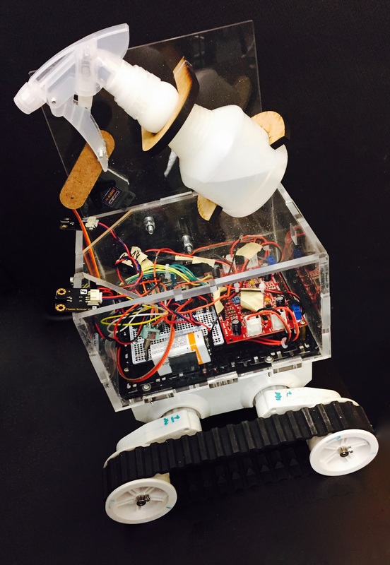
FireBotFireBot is a small, autonomous robot that will traverse rooms, detect small flames, and extinguish them using a safe, environmentally friendly, and easy to clean water system.
FireBot utilizes a five sensor system to detect physical obstructions and flames. This allows it to traverse rooms easily, avoiding things such as walls and furniture, until it senses a flame. It will then navigate towards the flame, stop approximately 6 in. away, and extinguish using our water system. FireBot is driven by a Rover 5 motor chassis and accompanying driver board, and the extinguishing system is driven by a hobby servo and a four bar linkage. The electronics and power sources are protected by a simple laser cut acrylic box. Below: Firebot demo videos |
|
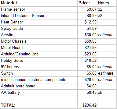
Bill of Materials
Our team was able to accomplish this project for approximately $100 in out of pocket costs due to our ability to borrow materials such as wall sensors, servos, and the motor chassis. However, it will take a similarly skilled team approximately $240 to purchase all required materials to construct FireBot. To stay true to original design, the team should ensure they have access to electrical prototyping tools such as a soldering station, and mechanical prototyping tools such as a lasercutter and drill press. A full Bill of Materials with some notes and prices is depicted left. |
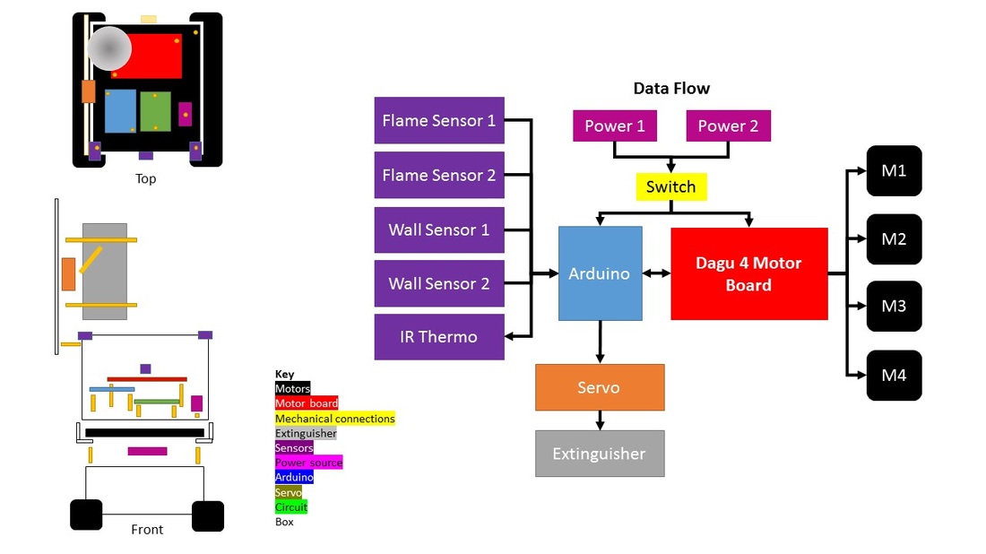
Integrated System Schematic
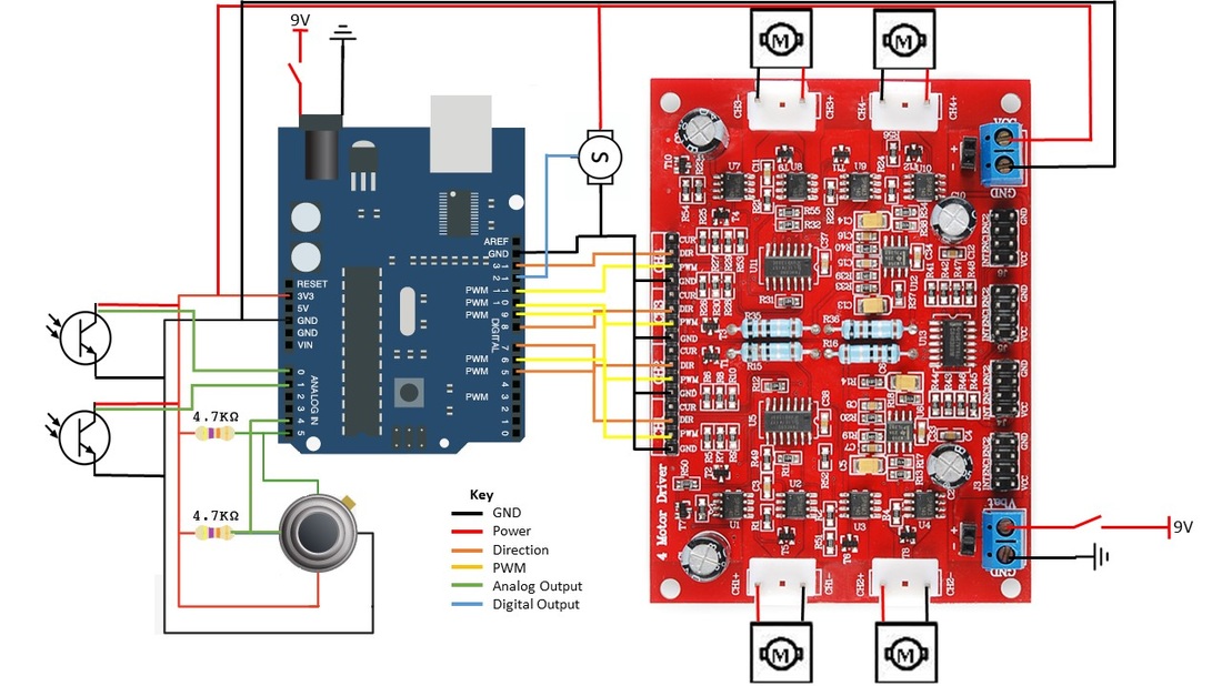
The final, fully integrated system has multiple interacting components. Mechanically, everything is mounted to the chassis via a standard issue mounting plate, and the sensors are mounted to our protective box via glue. Data flows from the sensors to the Arduino, which then communicates with a Dagu 4 Motor board to control the speed and direction of the four motors, allowing the bot to traverse rooms. The Arduino also interfaces directly with a servo, which in turn controls our extinguisher.
Scroll down to learn about each of FireBot's individual systems.
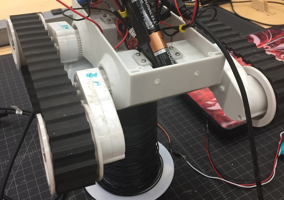
Mechanical SystemFireBot is driven by a Rover 5 Motor Chassis, which is approximately $50 in cost. However, we were able to borrow one for the duration of our project from an opensource robotics lab in the area, through a connection of Claire's. Claire then mounted all electronics and powersources on the chassis and developed simple control and test code, which was then iterated upon for a full controls system.
The protective box was developed and tested by Nicole and Julia working in tandem, and is made to mount to the motor chassis via the underside of the standard plate. It then has a lid to protect the electronics from our water extinguisher system. The water extinguisher system is mounted above the protective box and uses a mounted spray bottle driven by a hobby servo and a four bar linkage. The servo triggers the spray multiple times once flame is reached, allowing the bot to completely extinguish small flames. Click the buttons below to purchase the system components and download the CAD |
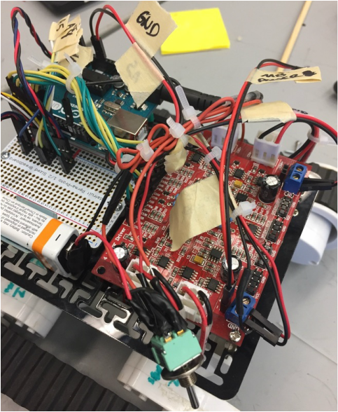
Electrical SystemThe electrical and sensor system was developed by Claire and Jules, with some testing assistance from Julia. The sensor system uses two infrared distance sensors to sense physical obstructions such as walls, two IR flame sensors to detect and navigate towards flames, and an infrared thermometer to detect proximity of flame and add resolution to our flame sensor direction system. The bot works very similarly to a line following robot: the IR flame sensors detect a specific wavelength of light that only occurs in fire, outputting an analog signal, allowing us to direct it towards that fire until the infrared thermometer stops the bot when it is close enough. The sensors are wired with a plug 'n play system to an adafruit proto board, which is then wired to the analog pins of an Arduino Uno. The Arduino is powered by a 9V battery, allowing the bot to be utilized apart from a computer, and has a power and ground line run to the motor board, allowing the boards to communicate with eachother. The motor board has power and ground from each of the four motors, and has a
|
direction, PWM, and ground signal for each of the four motors run to the Arduino's digital pins. The motor board is powered by a 9 V battery strip composed of 6 1.5V batteries. This power strip allows for longer battery life, as it has a combined 2000 mA-hrs as opposed to a single 9V battery's 200 mA-hrs. The power sources are wired to a switch, allowing the user to power the bot on and off easily. The entire electrical system is then mounted to the provided motor chassis plate, stabilizing the system and allowing it to withstand motion over time. The wires are color coded and labeled for user convenience.
|
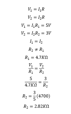
The sensors are each an analog output sensor, meaning that they essentially act as variable resistors depending on proximity of light, heat, or physical obstruction. To aid in the calibration of our sensors, Claire completed a simple Ohm's law analysis of each analog output sensor at a few discrete values. For example, pictured to the left is the Ohm's law analysis of the infrared thermometer sensing the temperature of the room as control, which is approximately 24 degrees C. Claire and Jules measured the voltage of the circuit before and after the sensor using a scope, pulling approximate values of 5V and 3V respectively. Claire then plugged those values and the given resistor value of 4.7K Ohms into Ohm's law to calculate the resistance of the sensor at room temperature.
|
ControlsFireBot's controls were developed by Jules, with some assistance from Claire for motor control and thermometer integration. The controls utilize the i2c, servo, and Dagu4Motor libraries to control the infrared thermometer, servo, and motorboard, respectively. Firebot went through several iterations of controller code, testing different portions of the sensor system as needed. We have individual programs to test and calibrate the infrared thermometer, flame sensors, wall sensors, and various levels of integration. Our final program utilizes all five sensors in the suite, using a collection of if/elif/else loops to control motion of the bot and extinguisher based off of i2c and analog flame sensor outputs.
|
Flame Sensor Calibration
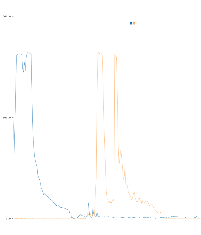
Pictured to the left is a calibration curve for each of our two analog flame sensors. Claire calibrated the sensors using a small candle flame. The two sensors are represented by blue and yellow lines, with analog output on the y axis and time on the x axis. As you can see, the yellow sensor starts completely blinded with an analog output of zero, this is because it was separated completely from the candle flame. Simultaneously, the blue sensor started approximately 6 inches away from the candle flame and has a very high analog output, which decreases with time, as it was distanced gradually from the flame. The blue sensor was then completely covered and separated from the candle flame while the same procedure was completed with the yellow sensor. This process was repeated several times and analog output values at several discrete distances were averaged to determine the final calibration values for FireBot's flame sensors. |
|
MVP Control
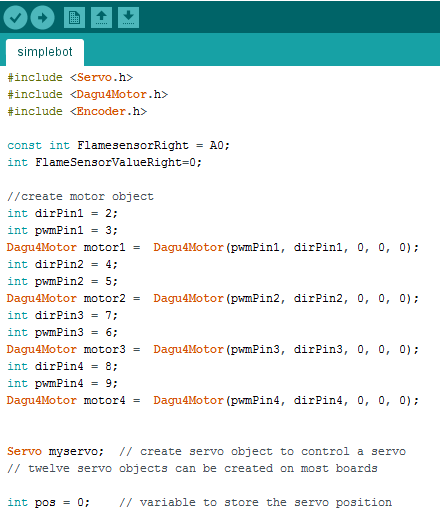
Our MVP utilized a very simple version of our sensor suite, and was developed by Jules with some contribution from Claire for chassis control and Julia and Nicole for servo control. The program begins by including libraries and initializing values for each of the two flame sensors. It then assigns the flame sensors to the Arduino's analog pins. Then, four motor objects are created using the Dagu4 motor library and assigned to motor pins. In the void setup(), a serial monitor is initialized to allow user monitoring of the analog outputs from the flame sensors, and the motor objects are assigned a speed and direction. The motors are then started, moving the bot forward. In the void loop() the analog output of the flame sensors is taken, and if a flame is detected via a cutoff value assigned during calibration, then the chassis is stopped and the servo oscillates 90 degrees repeatedly, triggering the water extinguisher system. |
|
Final FireBot Control
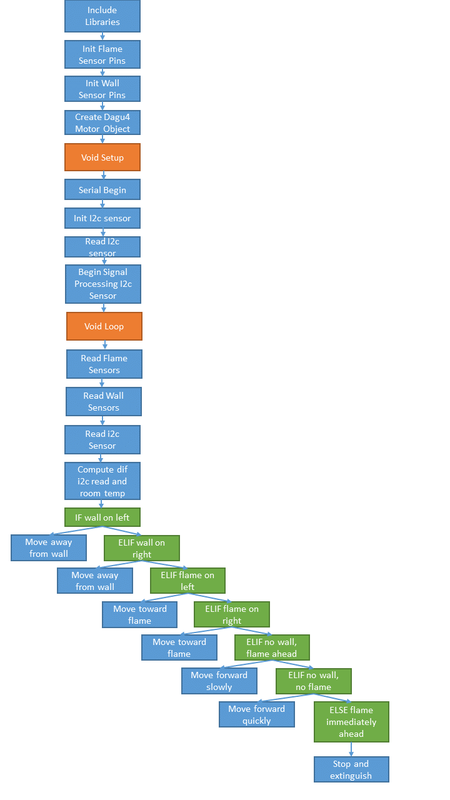
Our final controller code was developed by Jules with contributions from Claire for i2c sensor and motor control, and Julia and Nicole for servo control. It utilizes all five sensors in the suite, i.e. two infrared distance sensors, two analog flame sensors, and one infrared thermometer. The program begins by including libraries and initializing all of the analog sensor and digital servo pins. it then creates four motor objects using the Dagu 4 motor library. In the void setup() it begins a serial monitor, allowing the user to monitor analog outputs if needed. The program then initializes the reading and signal processing protocols for the i2c sensor, before moving into the void loop(). The void loop() begins by reading the values of each of the sensors and calculating the difference between the detected temperature from the i2c sensor and the user-set room temperature (we used 24 degrees C). It then enters an IF/ELIF/ELSE loop which detects direction of physical obstructions and flame, as well as distance of flame, and uses these values to command the chassis to follow a series of actions. For example, IF the wall is on the left, move to the right to avoid the wall. ELIF the wall is on the right, move to the left to avoid the wall, and so on. Once a flame has been detected via a large calculated difference from the infrared thermometer, the bot will stop approximately 6 in away (via user calibration) and trigger the servo to extinguish the flame. |
