Timeline
Week 1
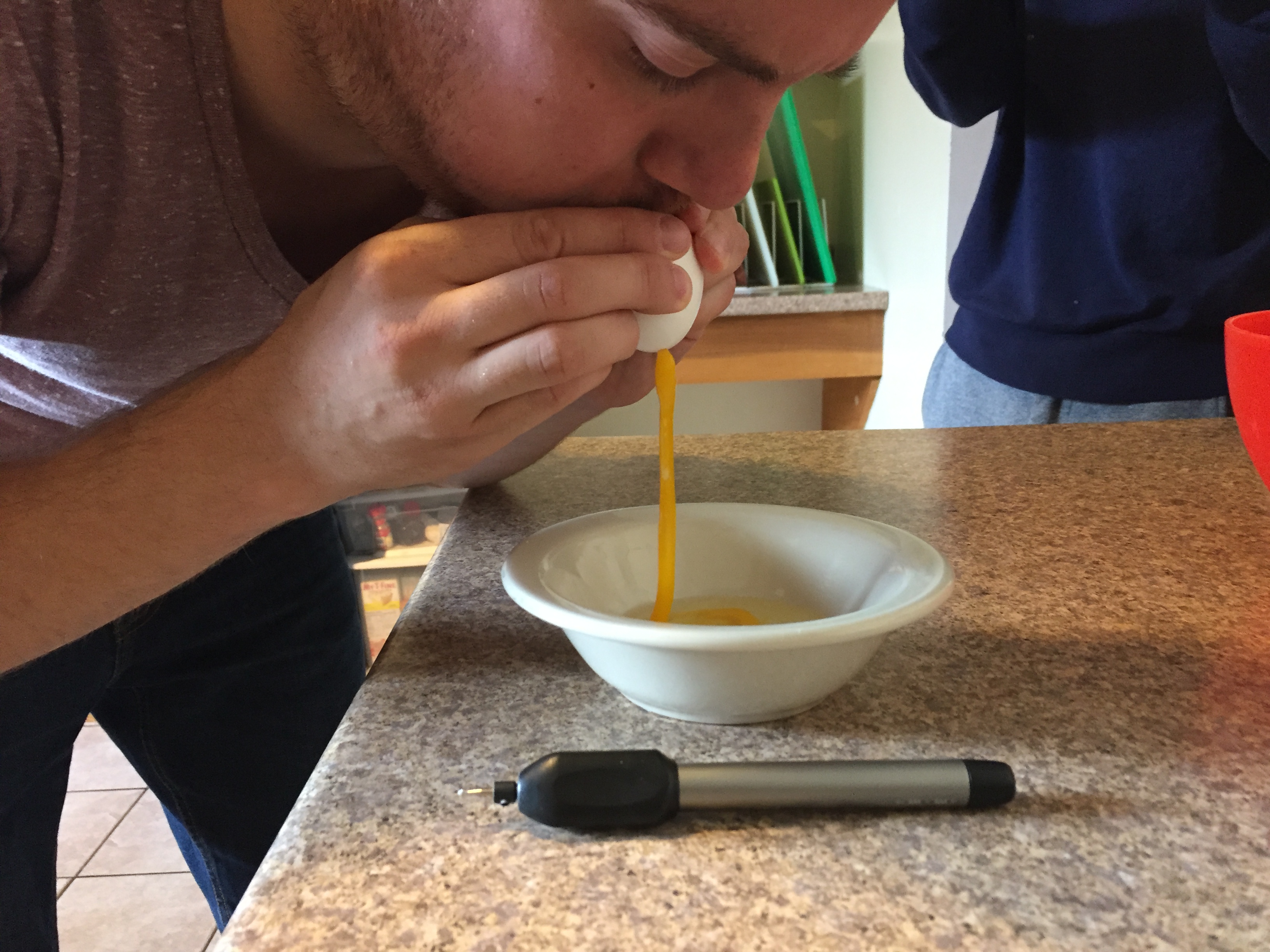
In order to explore drawing and carving for the project, we spent time emptying eggs and cleaning them out. We also bought a cheap Dremel clone to experiment with carving. It became immediately obvious that carving requires significantly more precision, power, and rigidity than drawing. So, we decided perfect drawing before moving on.
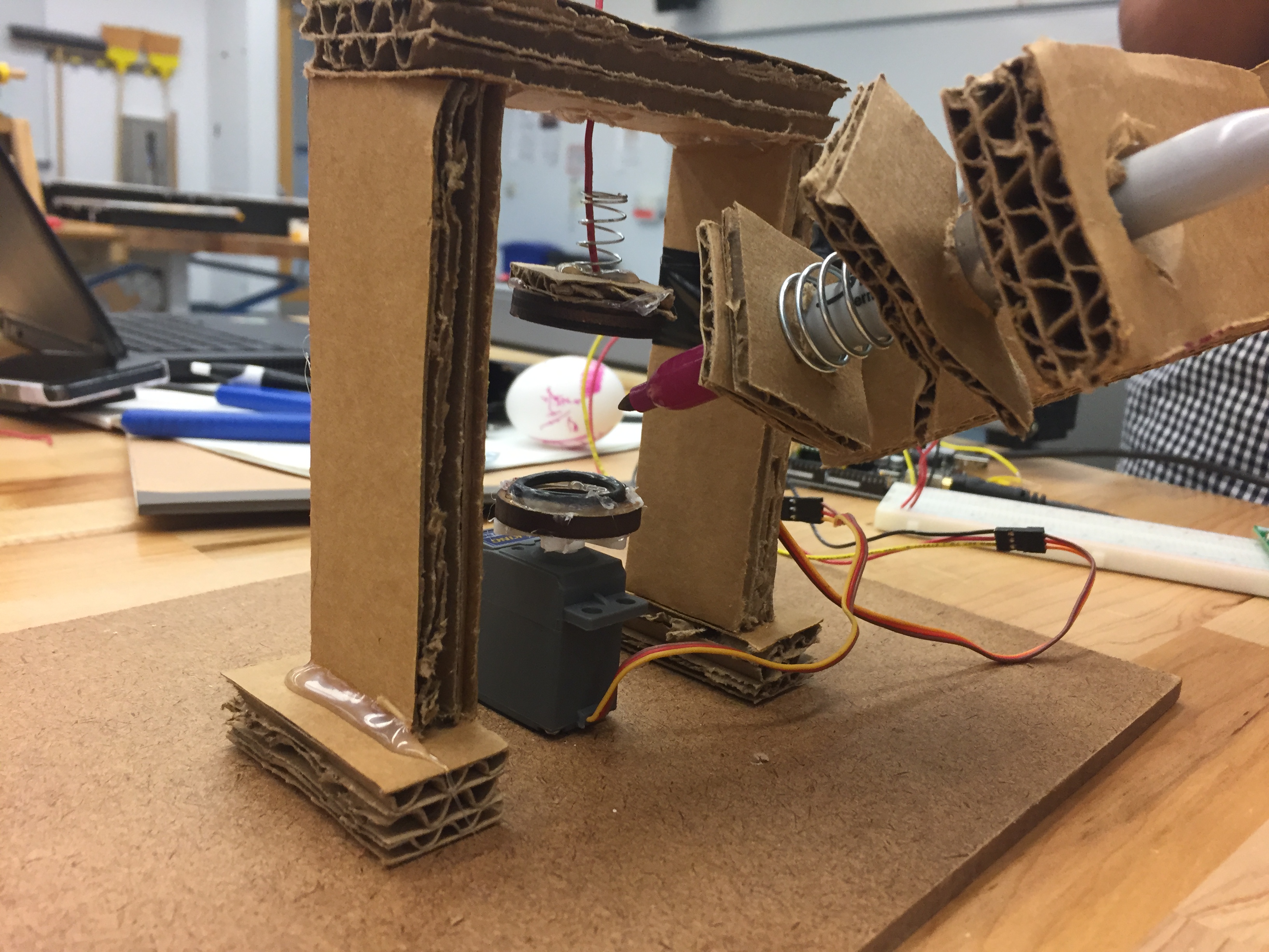
We built a simple cardboard model that resembled what we hoped our first working prototype would look like. Although the prototype was functionally useless, it gave us a clear idea of how to hold the egg, how big the frame should be, and what type of motors to use.
Week 2
Our software team dedicated most of their time during the first two weeks to research. In order to draw on eggs, we had to understand the math behind the different shapes that could be drawn on an egg, and develop a coordinate system that would work with the egg. We also evaluated the pros and cons of bitmap and vector graphics. By the end of the second week, we reached a point where we were confident with drawing shapes on an egg using vector graphics.
We began hardcoding drawing functions into arduino code and were able to draw some characteristic shapes on an egg through our first prototypes.
We also toyed with the idea of having a plugin within a SVG graphics editor that would be able to generate coordinates from any input shape. We dissected various extensions and scripts that work with parsing and generating coordinates from SVG graphics editors, and recreated segments of the code to explore their functionality.
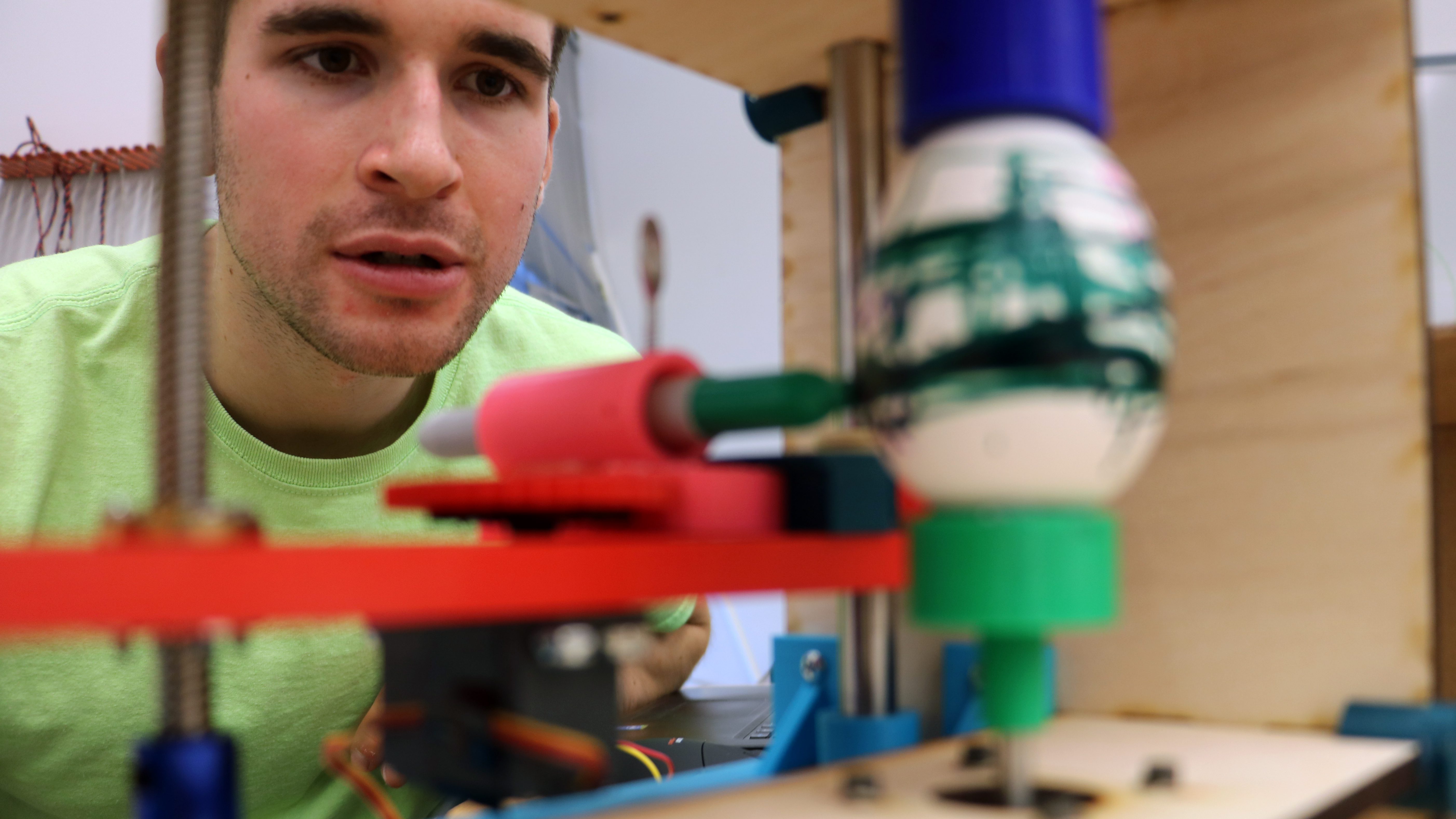
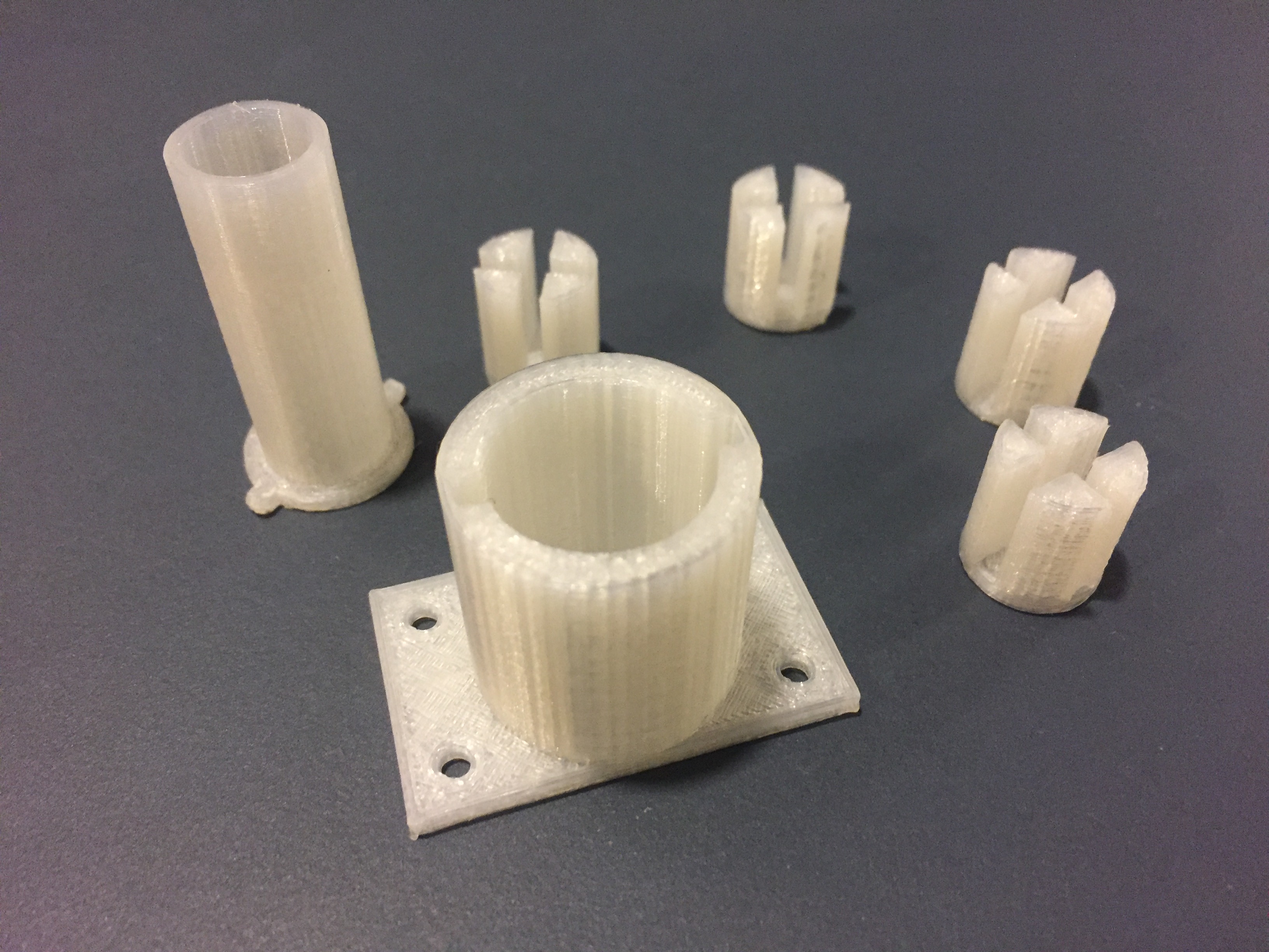
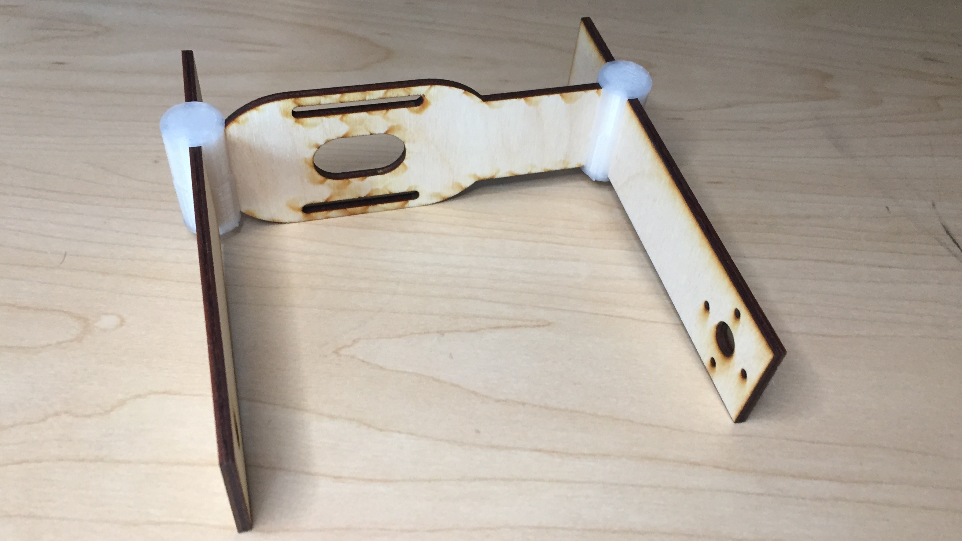
We scrapped the cardboard prototype, and built a new prototype from plywood and 3D-printed holders. We attached a servo motor to control a lever arm capable of moving a pen along the elevation axis. The prototype was ready for testing in the next week.

Week 3
With sufficient knowledge on the math behind coordinate systems, we started working on a script that extracts coordinates from cubic bezier curves. In the Arduino code, we modeled each bezier curve as a parametric equation.
We decided to stick with the Inkscape as our SVG graphics editor since it is open source, and supports user-made extensions. We began working on an extension that was heavily based on the MakerBot Unicorn code.
While the software team wrote functional arduino code, the mechanical team reiterated on the past prototype. After designing a new spring-loaded arm mechanism, we were capable of drawing various shapes using spherical coordinates.
Week 4
After dissecting the MakerBot Unicorn script, we completed a skeleton of the Inkscape extension. We also completed a script for converting bezier curves into coordinates, that, when plotted through matplotlib, resembled the original SVG image.
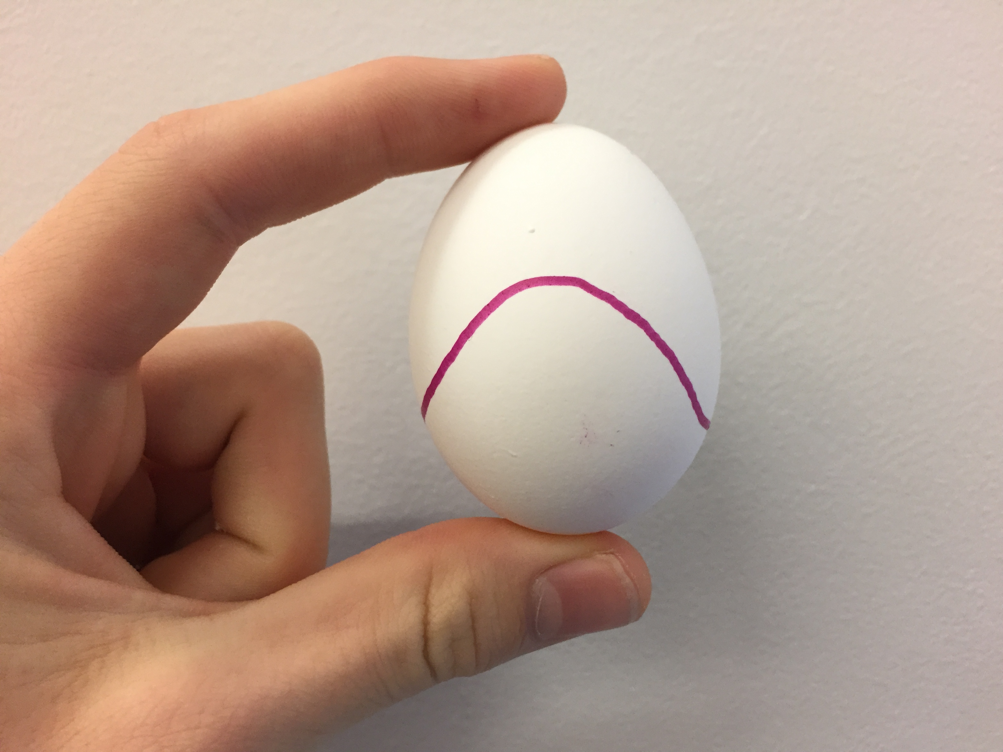
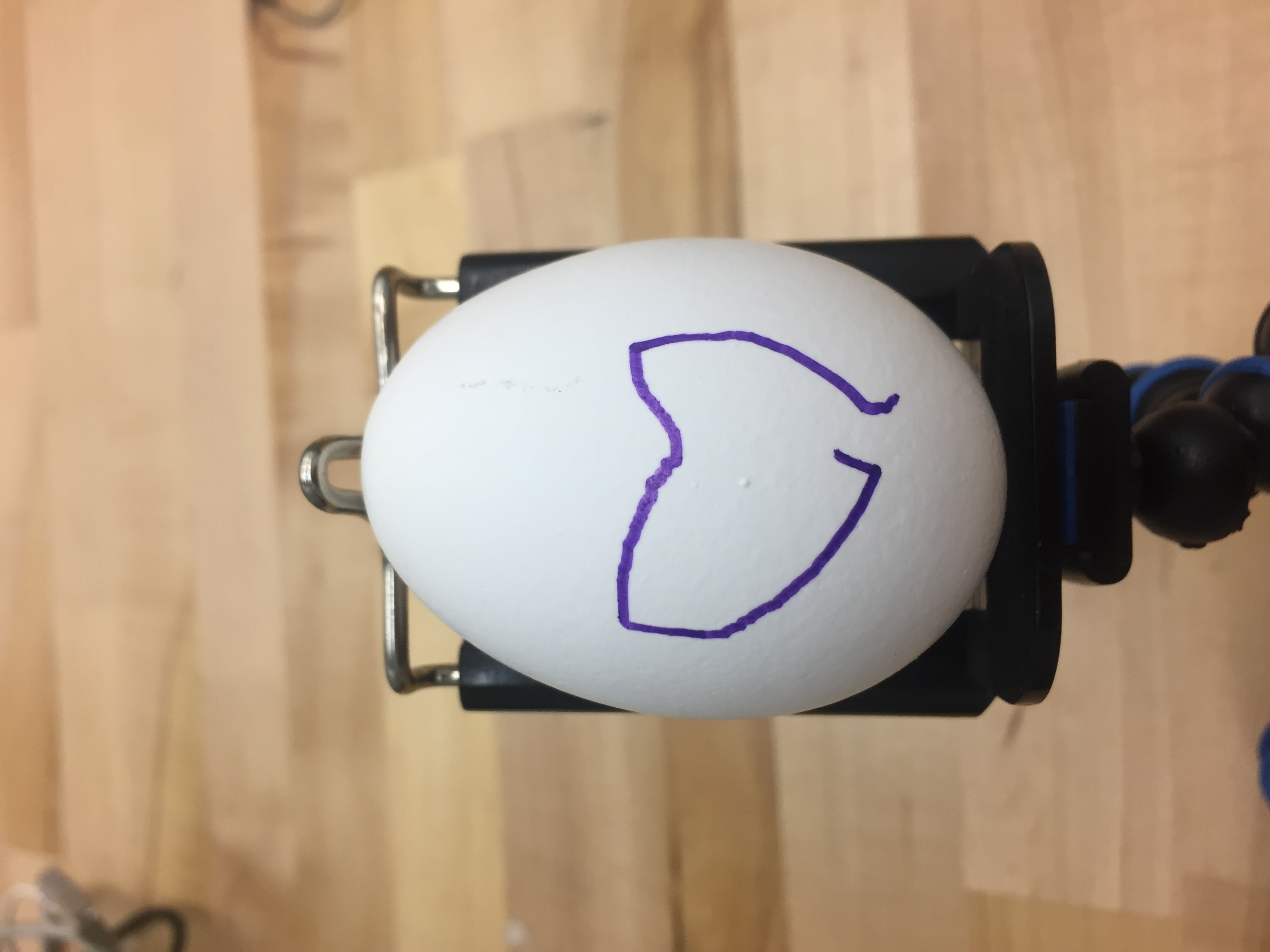
Our arduino code was able to reliably and accurately draw certain shapes and curves hard coded into the system. We attempted to recreate a heart from a SVG drawing onto an egg with moderate success. There were significant imprecisions around the edges. These imperfections were the results of a wobbly and poorly calibrated pen.
We also started planning for our third prototype. We decided to make the jump to cylindrical coordinates to reduce complications in the vertical axis. Spherical coordinates required a large lever arm which would be unstable and all around problematic. We decided to convert this to a linear axis.
Week 5
Numerous issues arose from the Inkscape extension code, and we decided to completely restructure the code, simplifying it to just two scripts. We also completed a parsing script that is able to collect key data on all SVG shapes for the Arduino to process. We started looking into serial communication.
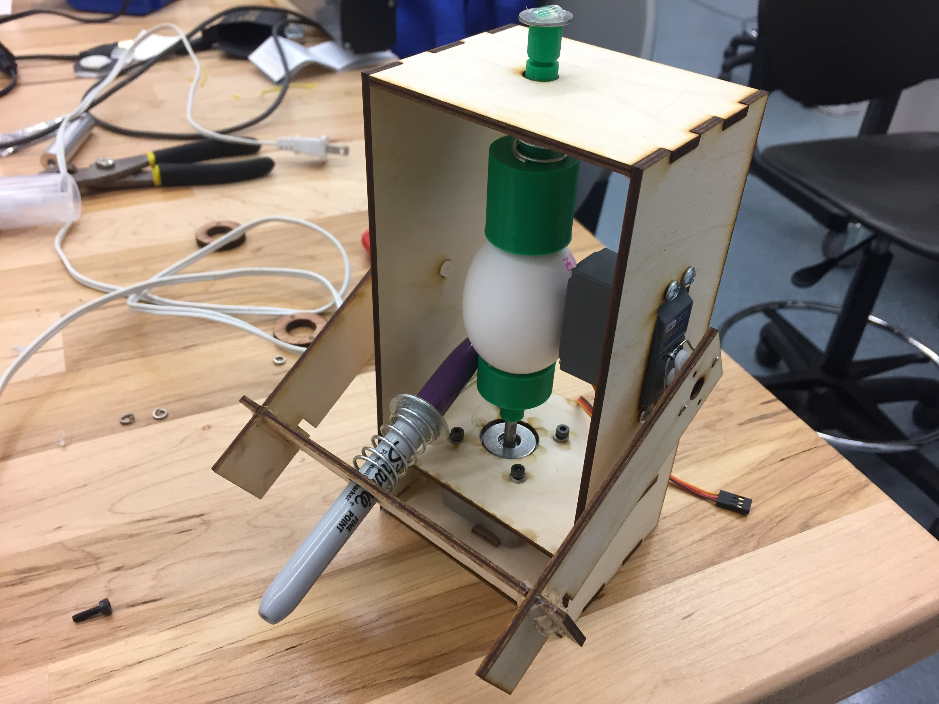
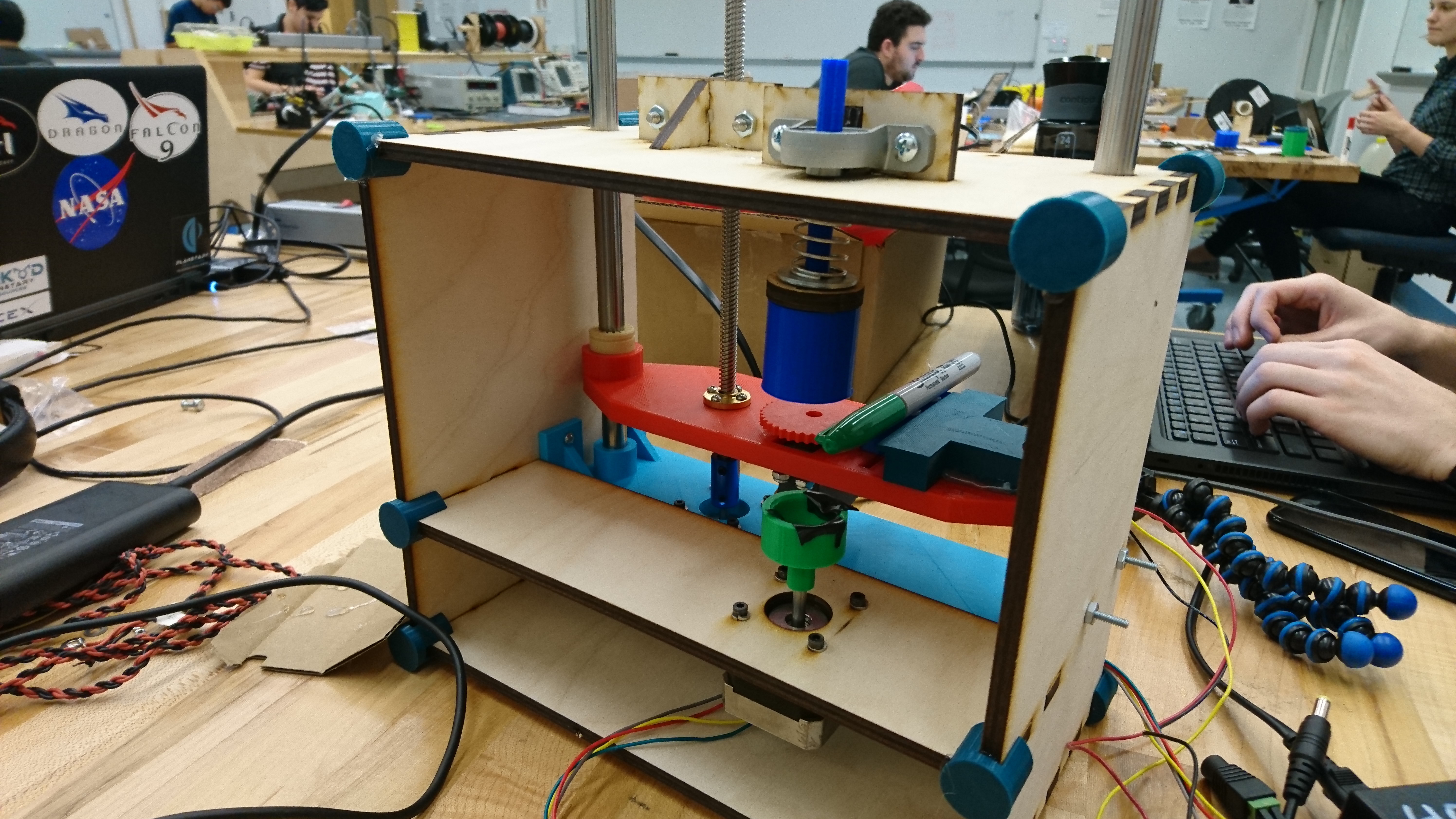
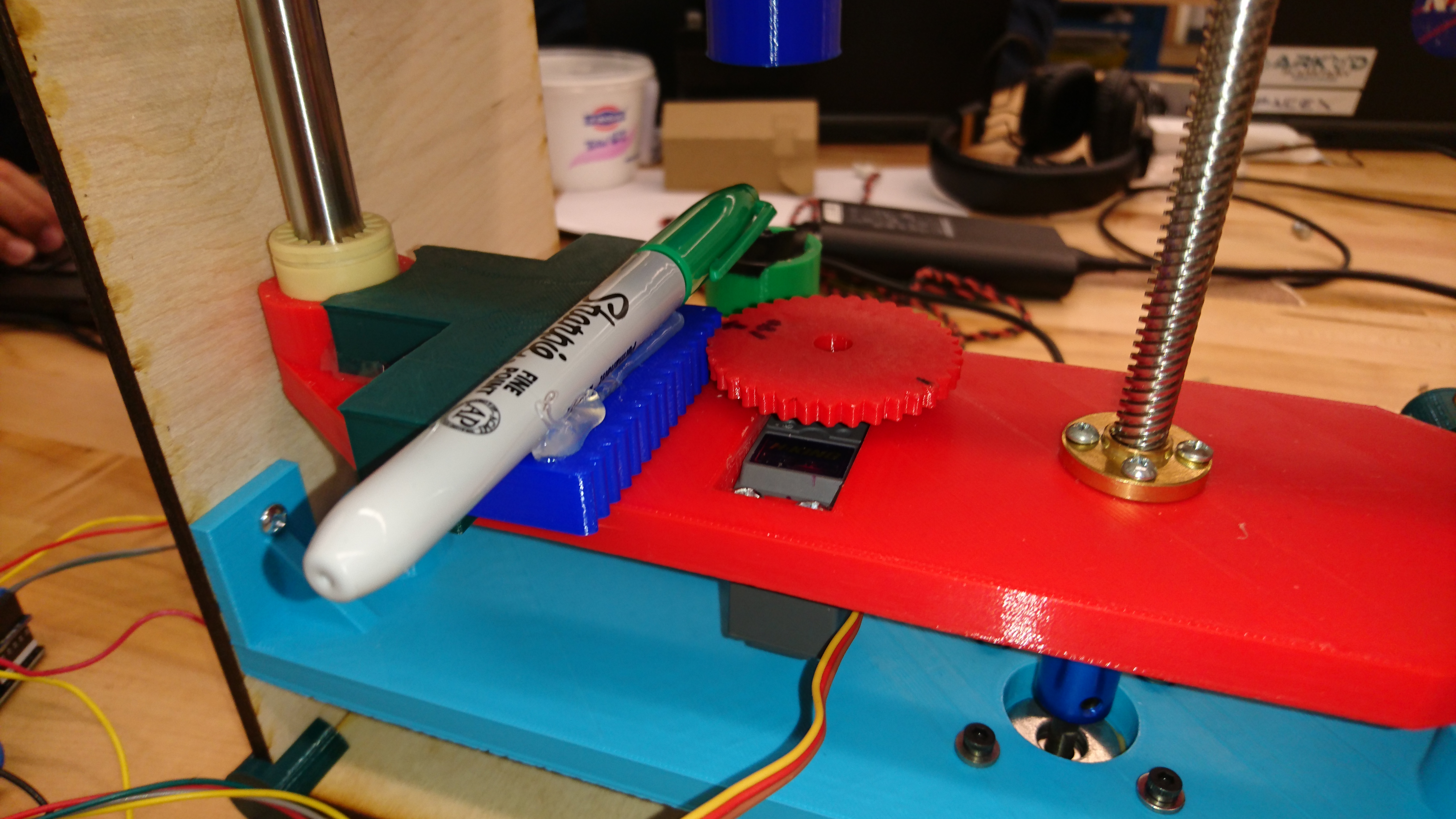
We completed the mechanical design overhaul.and implemented a lead screw mechanism controlled by a stepper motor. This major design change made our design significantly more robust and precise. However, it also required that we create a plunge mechanism for the pen to keep contact with the egg at all times. We attached the pen to a rack gear and used a servo to control its position.
Week 6
We finalized the Inkscape extension that was capable of creating a text file with coordinates for easy serial input into Arduino. All SVG parsing and drawing functions were integrated into the Inkscape extension itself.
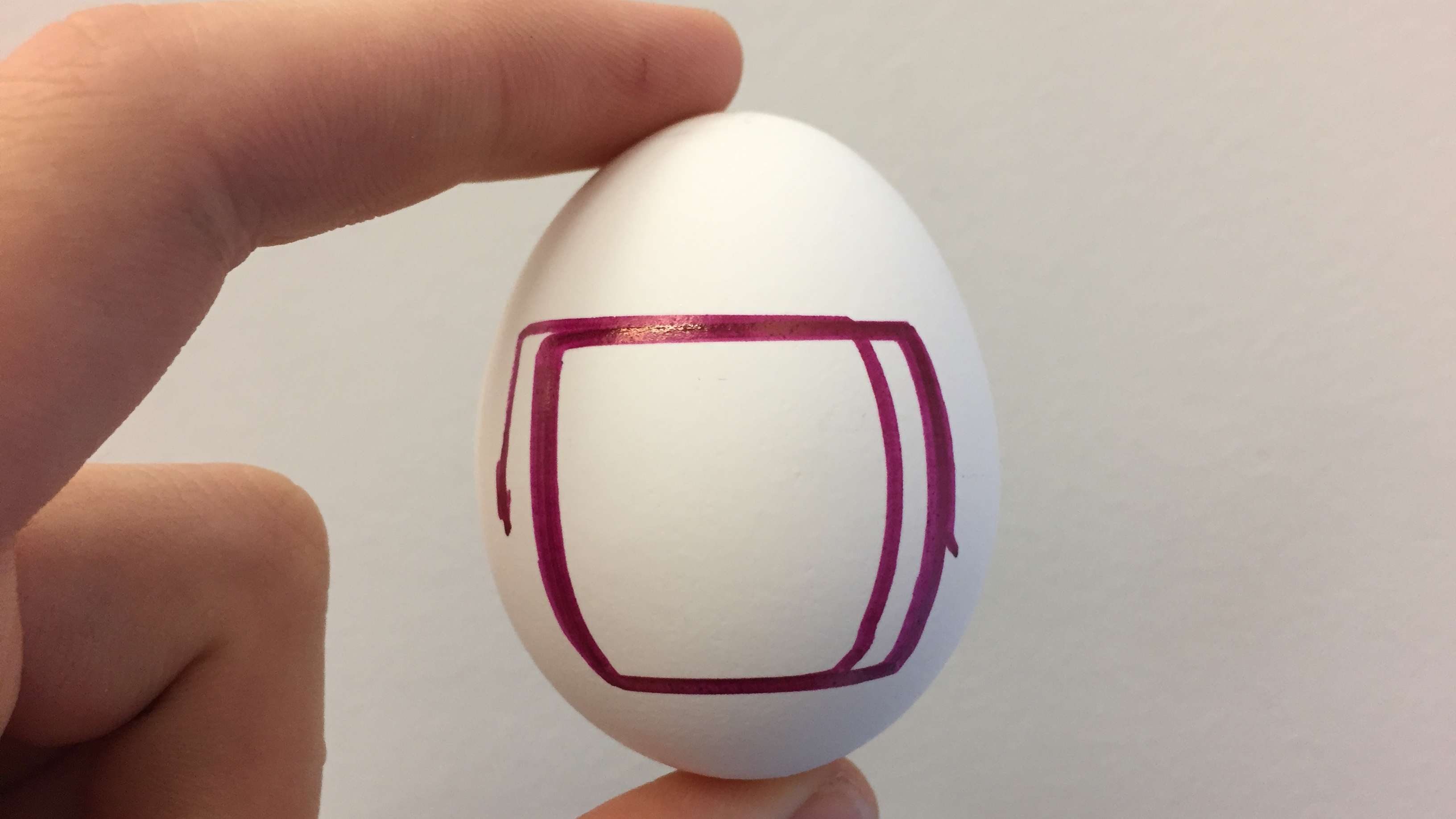
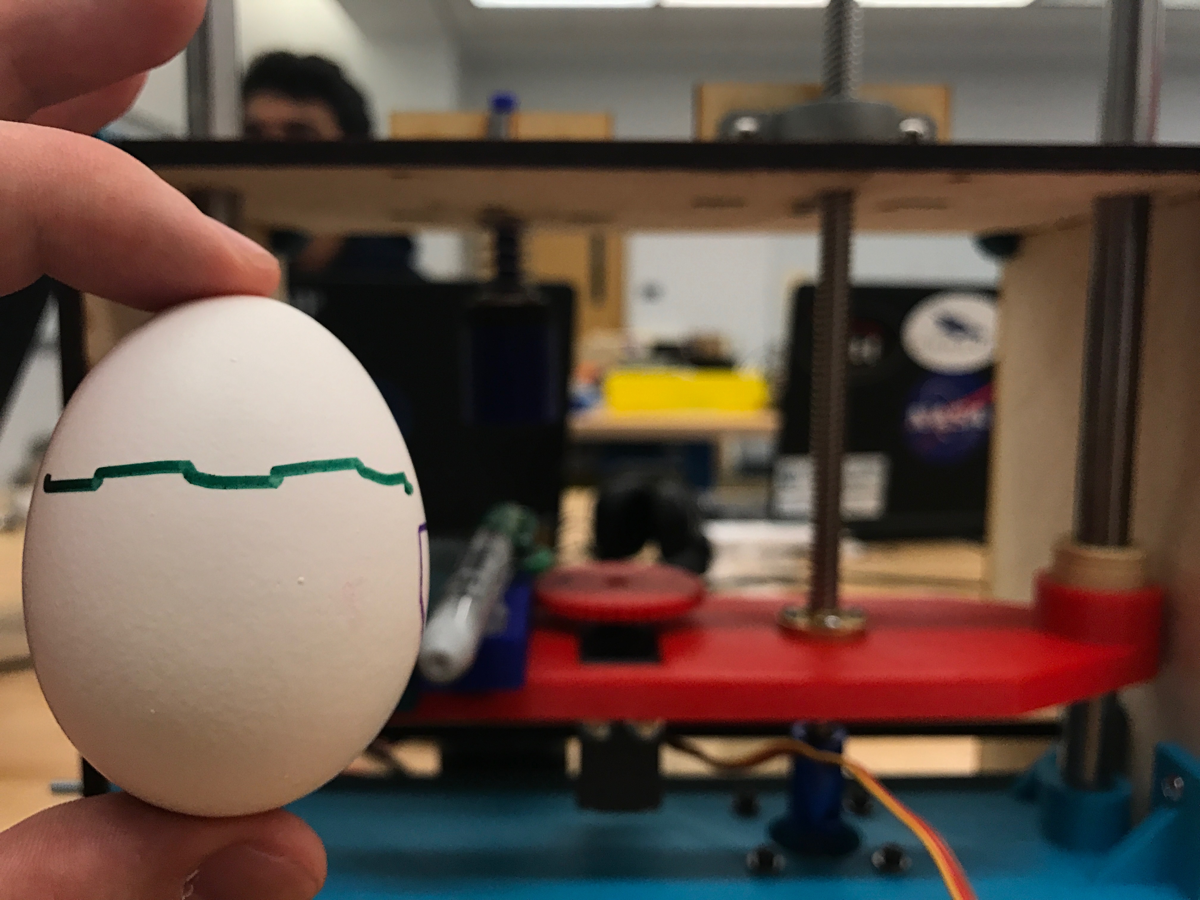
We also implemented functional serial communication between Arduino and Inkscape. This streamlined the testing process since drawings no longer needed to be manually written in Arduino code. Finally, the drawing functions were optimized to improve drawing speed, precision, and correct location on the egg. We managed to complete a small and precise drawing of a square wave.
Testing introduced several major mechanical issues. Without a spring mechanism on the pen to act as a buffer, drawing required a degree of precision we didn’t have. To deal with this, we prototyped a spring mechanism and mounted it. Unfortunately, this introduced some wobble intto our system, which became a major problem at higher latitudes. Occasionally, the pen would bend due to the curvature, which strained both the egg and the stepper motors.

Week 7
We decided to add a limit switch to the pen mechanism. This allowed us to detect when the pen was pressed against the egg, which is necessary for calibrating the pen prior to each drawing. This was originally a stretch goal, but turned out to be necessary since we underestimated the variance in egg sizes.
We polished all code, ironed out some bugs, and improved formatting. We added a calibration function that iterates through latitudes at a given intervals. The pen presses against the egg at each latitude until the limit switch is pressed, signalling the correct drawing depth at this latitude. This substantially improved the quality of our drawings and reduced the error between eggs of various sizes. We also integrated all segments of code with the Inkscape extension, making the entire drawing process streamlined.