The Basics
Over the last few months our mechanical sub-team has designed and built a wooden puppet with with vertical and lateral motion, actuated by eight motors, and held within a decorative case.
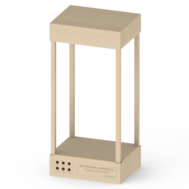
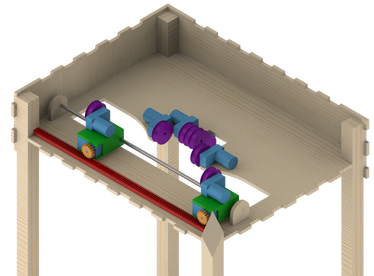
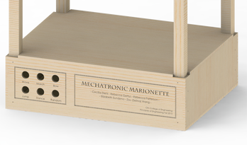
The case is made out of four 36" square dowels and laser cut pieces of 1/4" MDF and is held together with 3/4" #6 woodscrews. It has a 18"x14" footprint and is 38.5" tall. The top of the case is a hollow box that houses the motor plate with eight mounted motors. Four of these eight motors are being used in two motor sub-systems to enable lateral motion for the hands. Within the lateral subsystem, one motor spins a gear in a rack and pinion system, which changes the lateral position of the spooling motor mounted on top. We used a rod to hold the chassis level as the gear and spools turn, similar to how CNC and laser cutting machines function.
Our CAD and drawing files are located on GrabCAD, which you can find here:
https://grabcad.com/library/mechatronic-marionette-case-1
The Puppet

|
The final marionette puppet was designed with a simplistic model in mind. Taking inspiration from traditional marionettes there are five main motion points (waist, wrists, knees) and two stability points (shoulders). A combination of control over the waist and shoulders allows for torso motion while the wrists and knees control the arm and leg motions. All of the specific points, both motion and stability, are tied to eyelets with beading wire that spools in the top of the base. These spools are attached directly to the motor shafts, as the motors run the points are either raised or lowered. The marionette itself is a combination of hollowed out wooden components connected with fabric threaded through the arms, legs, and torso. While the joints have limited constraints they are forced into the correct motions and positions by the attached wires and subsequent tension. |
Spooling the Wires
|
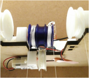
The marionette is controlled by a system of motor run spools. 3D printed from PLA, the spools are 1.25" diameter, with an inner diameter of 1", and enough width for the wire to continuously spool. We decided to use 0.008" beading wire to hang the marionette because of its durable and flexible characteristics. The beading wire does not hold its shape allowing us to easily retain the desired tension without risking the wire falling off of the spools.
All of the puppet's main motion points (waist, wrists, and knees) other than the stability points (shoulders) are connected to single spools. Since the stability points always move together they are connected together on a double spool, shown to the right. |
|
Lateral Motion : Rack & Pinion
|
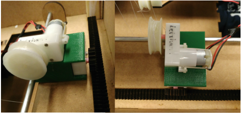
While the spools allow for controlled vertical motion we needed to incorporate lateral motion in order to replicate traditional marionette movements.
To actuate lateral motion of the hands we designed a two motor rack and pinion spooling system. Using a 3D printed chassis we were able to vertically mount two motors for each hand. One motor spins a gear along a rack, this controls the lateral position of the spooling motor which is mounted on top. We used a 1/4" zinc plated rod to hold the chassis level. |
|
|