With the mechanical system complete, we calibrated the code to control the motions correctly via the motors and rack and pinion. We also tested that the new buttons worked with the rest of the electrical system and resulted in the production of the correct motions (we made sure that the 'jump' button didn't cause a 'march' motion when pressed). We also switched over from a breadboard to soldered electrical components for a more durable end product. We created the decorations for the marionette case and hid the electrical and mechanical components within the top and bottom of the case so that they would not detract from the aesthetic. Lastly, we finished the website and documentation, so that future teams can see what we did and how we did it. Because we continously integrated throughout our previous sprint, most of the work in this sprint was simply assembling and testing new components against each other and smoothing out flaws.
|
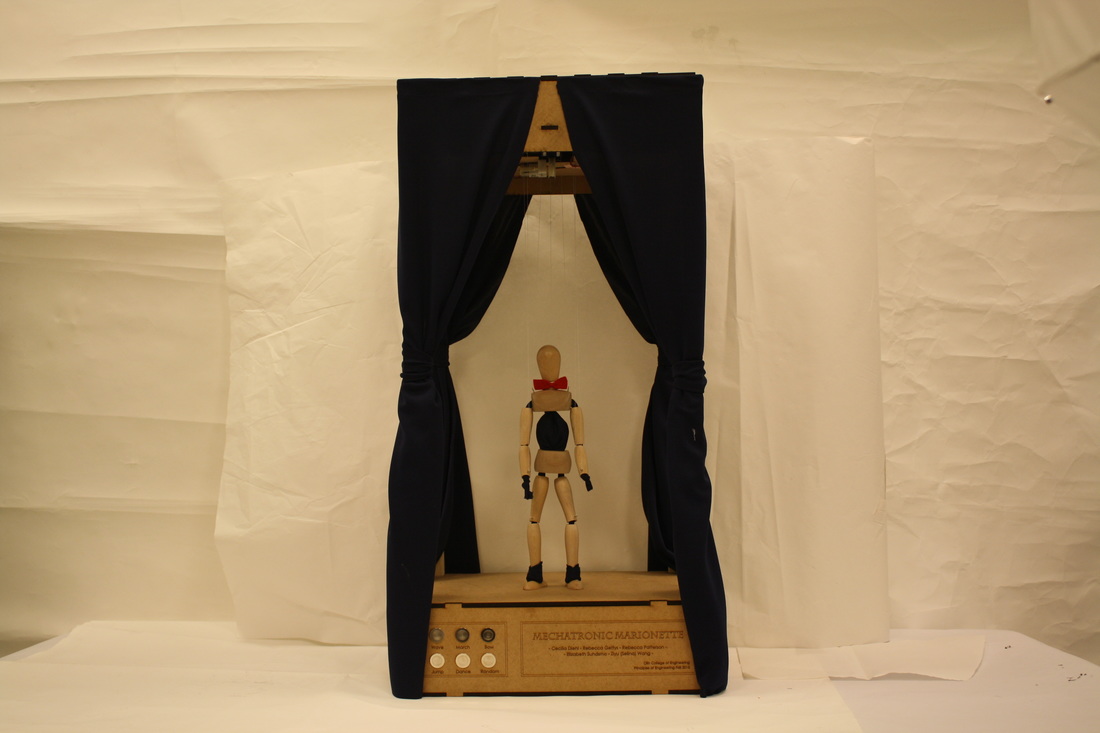
In the final sprint, we assembled our final marionette and electrical systems and tested them in conjunction with the code; we finalized the mechanical design, which was mostly the same from last sprint, and constructed the final marionette and case. A major design change this sprint was switching from a two motor plate design to a single motor plate design. We did this by only using the the rack and pinion system for the lateral motion in the arms, instead of arms and torso. The rack and pinion system works as expected, although occasionally over or undershoots slightly due to the low quality of motors used. A major takeaway for a future team building this project is to use servos or less cheap motors because they are able to be more accurately controlled.
With the mechanical system complete, we calibrated the code to control the motions correctly via the motors and rack and pinion. We also tested that the new buttons worked with the rest of the electrical system and resulted in the production of the correct motions (we made sure that the 'jump' button didn't cause a 'march' motion when pressed). We also switched over from a breadboard to soldered electrical components for a more durable end product. We created the decorations for the marionette case and hid the electrical and mechanical components within the top and bottom of the case so that they would not detract from the aesthetic. Lastly, we finished the website and documentation, so that future teams can see what we did and how we did it. Because we continously integrated throughout our previous sprint, most of the work in this sprint was simply assembling and testing new components against each other and smoothing out flaws.
0 Comments
With our last few weeks rapidly drawing to a close, we have completed our last shopping runs and filled out our final online ordering forms. Over the course of this project we have spent $220.71 of our $250.00 budget. Our purchases were from Amazon, Adafruit, Home Depot, and Joanne’s. We bought spares of a few items at the time of purchase, such as the screw eyelets and motor shields, in case something broke or went wrong. We used one of our 2 packages of eyelets and 2 of our 3 motor shields. We were also able to obtain scrap wood and foam for our earlier iterations from the stockrooms, and later used PLA from Olin to 3D print our spools and chassis. Throughout the project we have used motors supplied by Olin’s Mech-E stockroom, and electrical components from the ECE stockroom, both of which are free resources to Olin students. For a breakdown of how we spent our budget please see our bill of materials, attached below. List of Materials Present in the Final Product: - ¼” MDF, 2 sheets of 2’x4’ - 4 1” square dowels, 38” long - 1 zinc plated rod 36” long ¼” diameter - 1 pack of 100 woodscrews #6 ¾” (used 40) - 1 drawing mannequin, 18’’ - 1 pack screw eyelets (used 7) - 50 yds beading wire D=0.008 (lots to spare) - 2.5 yds fabric - 2 motor shields - 1 arduino uno - 6 buttons (Momentary N.O. push button) - 1 power supply - 8 BO2 motors - Circuit components - 10 yds electrical wire - 10k ohm resistors (one resistor per button)
For the last sprint, the main goal of the software system is to program all the motions we need.
We finalized on nine motions: 0: STOP, 1: Wave, 2: bow, 3: jump, 4: march, 5: hip drop dance, 6: drop dead, 7: shopping cart dance, 8: fly, 9: sprinkler. The first five motions correspond to the first five buttons on the control panel. The rest are specific to the random button. All motions are programmed and tested. The way we are choosing random motions is using the RandomSeed function in void setup() and the random function in void loop(): void setup () { // if analog input pin 0 is unconnected, random analog // noise will cause the call to randomSeed() to generate // different seed numbers each time the sketch runs. // randomSeed() will then shuffle the random function. randomSeed(analogRead(0)); } void loop () { if(button6.IsPushed()){ mode = round(random(1,10)); } } The direct link to all sprint 4 scripts are here: Sprint 4 Scripts The direct link to the sprint 4 Arduino file is here: Sprint 4 All Motions In sprint 3, we built a basic electrical system, consisting of an Arduino controlling 10 motors via 3 Adafruit motorshields; this system worked, but we were still controlling the motions via serial bus off of our laptops, but we certainly didn't want that for our final project. Previously, we had used a single button to cycle through motions, which was also not the desired behavior. We wanted one button per motion so that it is easy and intuitive for a user to interact with.
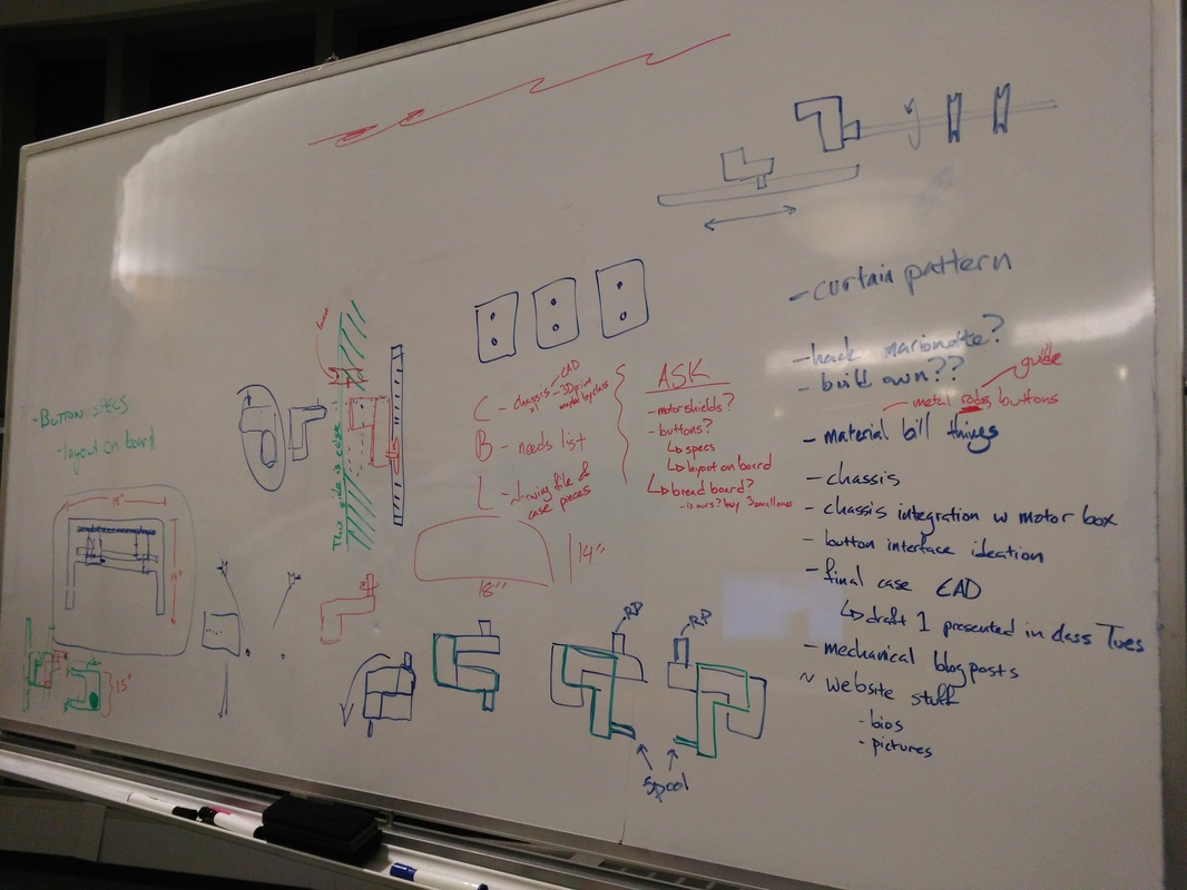
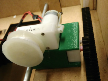
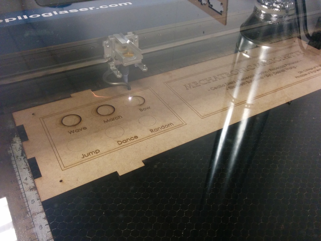
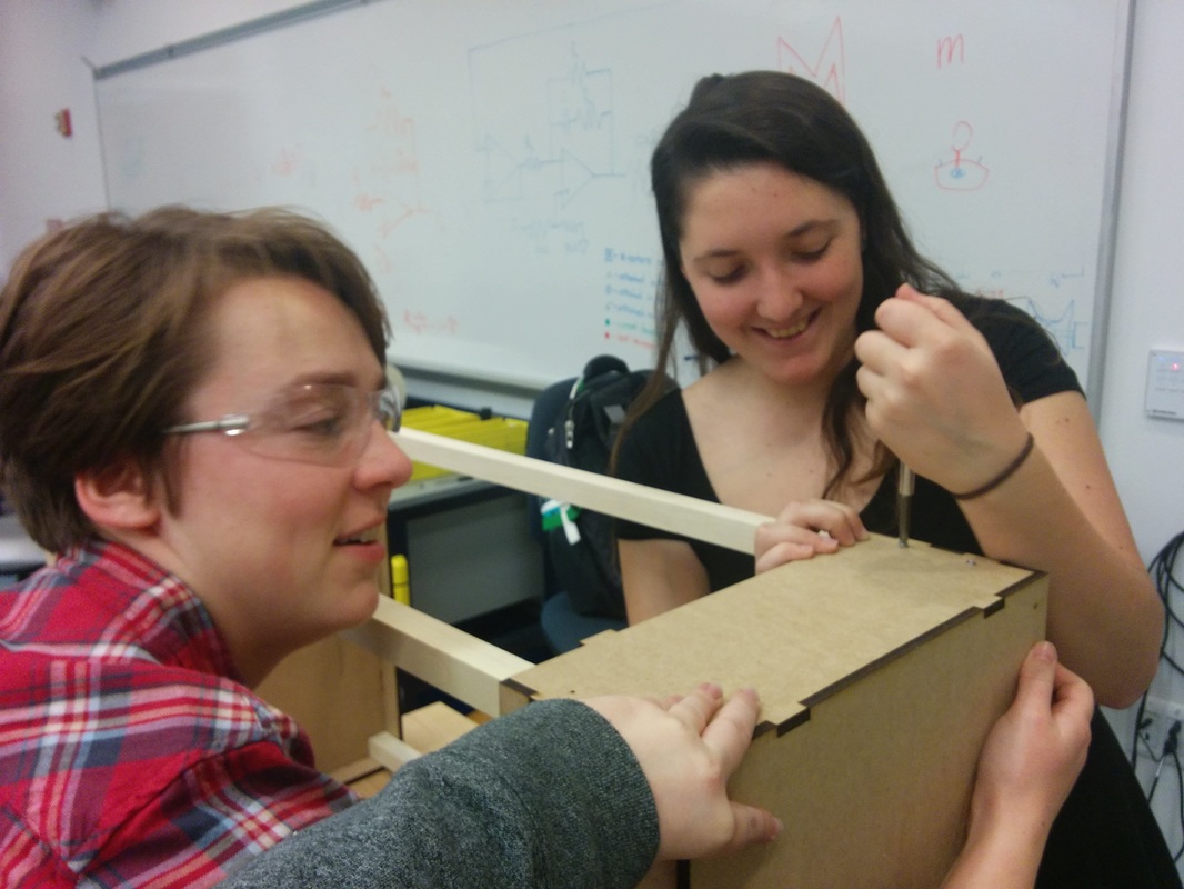
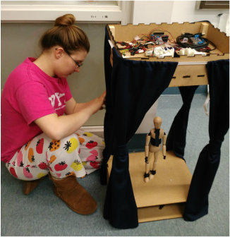
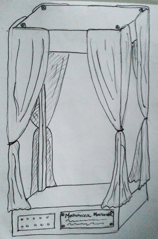
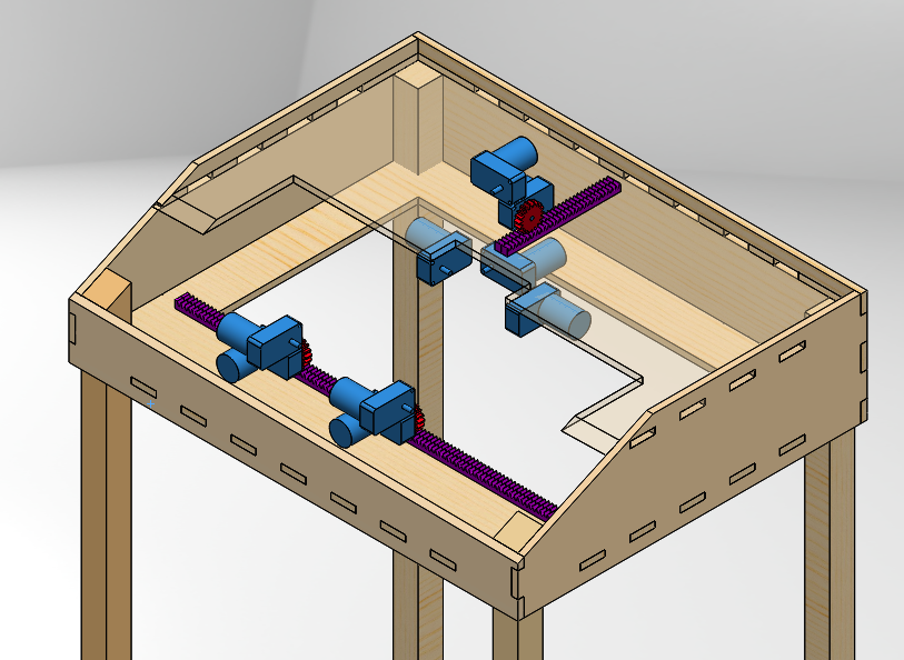
In addition to the motors/motorshields/arduino assembly that we build in sprint 3, we also built 6 identical circuits on a breadboard to be used for the buttons. These circuits would be closed when the button was pressed, and the input to the Arduino was positioned to pick up on this change. We used an Arduino library, EasyButton, to interpret the inputs from all 6 buttons, and change the marionette's motion appropriately. We got this working after some bugs; for sprint 4, all that is left on this part of the electrical system is button replacement with the final buttons (in this sprint we used the tiny PoE buttons) and some wiring to make things fit inside our project. It's time, time to assemble! Kinda... Coming into Sprint 4 the mechanical sub-team had a lot to do, but once we had our final puppet built we were feeling motivated and excited! The next thing we had to focus on was actuating everything else :P Our first step was to actuate the lateral motion of the hands. It took us a few meetings to come up with a finalized design for our rack and pinion chassis. We ended up vertically mounting two motors for each hand. One motor spins the gear along the rack, this controls the lateral position of the spooling motor which is mounted on top. We used a 1/4" zinc plated rod to hold the chassis level. Once we had the lateral motion we moved on to assembling our final case. This involved laser cutting out all of the pieces and screwing them together with a combination of detailed finesse and brute force. During this step we also worked with the electrical sub-team to place the motors. We redesigned the top box to hold the motors on one level instead of two. We then moved on to beautification! This involved designing and creating the curtains for the case. The curtains serve two main functions; the first of which is visual appeal, the second, hiding unwanted wires. Originally we were going to cover the four posts as well as the top, however some unforeseen complications arose (namely needing to be able to access the top box) and we decided to forgo covering the top so we could continue to open the top box.
In the previous sprint (sprint 3), we assembled and tested our complete electrical system. This consists of an Arduino connected to 3 Adafruit motor shields which control 10 motors, and 6 push buttons connected to the Arduino via a breadboard. We used tiny PoE buttons and the PoE motorshields to test, and got everything working.
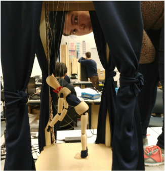
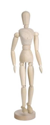
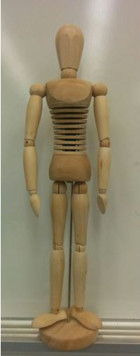
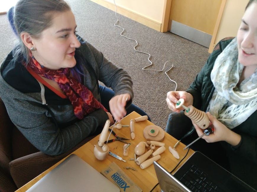
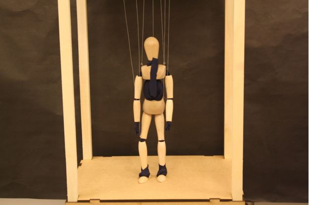
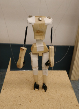
In sprint 4, we finally received our buttons and motorshields for the final project. We assembled the button interface for the front of the case and soldered and prepped the motorshields for use. We wired the motors to the motor shields. We also wired the buttons to the circuit used for the Arduino input on the breadboard. Lastly, we hooked the Arduino and motorshields up to our power supply. It should be noted that we reduced our design to include to 8 motors and 2 motor shields in this sprint due to some simplifications in the code and mechanical design. This system can be seen in the picture below, and is the final electrical system that ended up in our project. Since this was our last sprint, we had to finalize our puppet. We had started looking into finalizing our puppet in Sprint 3 because we were concerned about the amount of time it had taken us to fabricate the last puppet from scratch and knew that the final puppet would take us even longer. After looking into some other options, we settled on ordering a drawing mannequin that we could alter to have a loose torso and joints. The mannequin we ordered was supposed to have a solid wooden torso like in the picture on the left below. However, the one we received had a “spine”- its torso was composed of a thick wire and a series of wooded disks. It is pictured below on the right. This left us with a dilemma. We could not cut the torso apart in the woodshop because it contained metal, but we couldn’t cut it in the metalshop either because it had wood. At this point, we decided to set aside finishing our puppet until Sprint 4 so we could work on other aspects of the project. So during this sprint we had to approach the idea of making the mannequin into a marionette again. Eventually we managed to take it apart using screwdrivers, pliers, and brute force. The spine’s internal components are shown below. Once we had all the pieces separated, we had to decide how to reassemble them to work for our purposes. During disassembly, we discovered that all the limbs of this mannequin were hollow, and this is what led us to our final design. We used fabric to run through the limbs and connect the top of the torso to the hips. This made the joints and torso flexible, just as we needed. The hands were replaced by knots in the fabric at the ends of the arms, which added character to our puppet.
Wooden dowels were attached to the mannequin's original feet and slid into the hollow legs, where the fabric gripped the dowels so that the feet did not fall out. After that, we added eyelet hooks to the wrists, knees, shoulders, and tailbone. Then all that was left to do was string the puppet up! Now that we've reached the end of Sprint 3 what do we want to do to keep moving forward? Since this is our final sprint it's time to think about final decisions and assembly, as well as any tasks we see as possible risks that might cause problems as we continue on.
During our last meeting we came up with our tasks for this final sprint and what we think needs to be done to complete this project. The first item is the construction of our final base. This involves multiple sub-tasks since we still need to laser cut the cadded parts, assemble our final motor lineup (including the rack & pinion), and finalize stage appearance (curtains, plaque, etc.) Mechanically we also need to finish designing and building our final wooden puppet, in this case we plan on using parts from a wooden drawing mannequin. Aside from these tasks we also need to finalize our control system. To do this we will be integrating our new buttons into the final case design and looking into how we could incorporate voice control. There are a few possible risks that we think are important to think about in order to prevent complication later in Sprint 4. Our first main concern involves how we are controlling the puppet (buttons or voice control). While we have tested and worked with our current buttons we just ordered a new variety and need to go through that testing and integration again. As for voice control we merely have a lot of research ahead of us to figure out if this is even a feasible task to set. Mechanically we also have a few concerns with lateral motion, since we haven't completed this part of the design yet, as well as the fact that our motors seem to over-run, requiring a lot of calibration. While we do have a lot to do and will inevitably come up against unforeseen challenges we are excited to push on strong into our final sprint! The goal of the software system for this sprint is to set up the six buttons as well as all ten motors.
For controlling all ten motors, we are using three stacked Adafruit MotorShields and initializing the corresponding motors with the correct locations. #include <Wire.h> #include <Adafruit_MotorShield.h> #include "utility/Adafruit_PWMServoDriver.h" // Create the motor shield object with stacking addresses Adafruit_MotorShield AFMSMotorShield1 = Adafruit_MotorShield(0x60); Adafruit_MotorShield AFMSMotorShield2 = Adafruit_MotorShield(0x61); Adafruit_MotorShield AFMSMotorShield3 = Adafruit_MotorShield(0x62); // Initiate the motors controlling the left and right side of the body Adafruit_DCMotor *lefthandMotor = AFMSMotorShield1.getMotor(1); // Motor 1 Adafruit_DCMotor *righthandMotor = AFMSMotorShield1.getMotor(2); // Motor 2 Adafruit_DCMotor *leftfootMotor = AFMSMotorShield1.getMotor(3); // Motor 3 Adafruit_DCMotor *rightfootMotor = AFMSMotorShield1.getMotor(4); // Motor 4 Adafruit_DCMotor *laterallefthandMotor = AFMSMotorShield2.getMotor(1); // Motor 5 Adafruit_DCMotor *lateralrighthandMotor = AFMSMotorShield2.getMotor(2); // Motor 6 Adafruit_DCMotor *rightshoulderMotor = AFMSMotorShield2.getMotor(3); // Motor 7 Adafruit_DCMotor *headMotor = AFMSMotorShield2.getMotor(4); // Motor 8 Adafruit_DCMotor *leftshoulderMotor = AFMSMotorShield3.getMotor(1); // Motor 9 Adafruit_DCMotor *bottomMotor = AFMSMotorShield3.getMotor(2); // Motor 10 Adafruit_DCMotor *spare1Motor = AFMSMotorShield3.getMotor(3); // Motor 11 Adafruit_DCMotor *spare2Motor = AFMSMotorShield3.getMotor(4); // Motor 12 In order to control multiple buttons, we tried debouncing them ourselves first. However, we didn't have much success with it even with several attempts. We therefore moved into the direction of using user libraries. We first found this library called Bounce2. It didn't turn out to be very effective, we then tried using the Button library. It was a pretty powerful library; however, the user interface wasn't very friendly. We then found a very light and user-friendly library called EasyButton. We finalized our code with this wonderful library: #include <EasyButton.h> const int buttonPin1 = 5; const int buttonPin2 = 6; const int buttonPin3 = 7; const int buttonPin4 = 8; const int buttonPin5 = 9; const int buttonPin6 = 10; EasyButton button1(buttonPin1); EasyButton button2(buttonPin2); EasyButton button3(buttonPin3); EasyButton button4(buttonPin4); EasyButton button5(buttonPin5); EasyButton button6(buttonPin6); void loop { button1.update(); button2.update(); button3.update(); button4.update(); button5.update(); button6.update(); if(button1.IsPushed()){ mode = 1; } if(button2.IsPushed()){ mode = 2; } if(button3.IsPushed()){ mode = 3; } if(button4.IsPushed()){ mode = 4; } if(button5.IsPushed()){ mode = 5; } if(button6.IsPushed()){ mode = 6; } } The direct link to all sprint 3 scripts is here: Sprint 3 Software The direct link to our Arduino File is here: Sprint 3 Final Script Going into this sprint we had hoped to have our final case CADed and built to give our software team something to work with, but we fell a bit short of that lofty goal since we gave ourselves a lot of tasks to do.
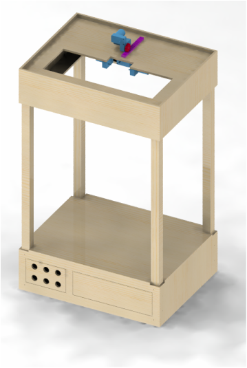
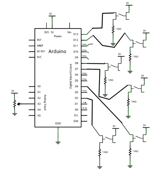
Ultimately we designed a case with a two plate motorbox. We chose to have a multi-layer, and therefore taller, motorbox because it would give us more space to mount lateral motors and avoid tangling lines. Currently we plan on having 3 motors that travel on rack and pinions, enabling lateral motion (in addition to vertical motion from spooling). These lateral motors would control the strings attached to either hand and the torso, and would make motions like waving and bowing more realistic. In addition to these lateral capability motors, which are really two motors working together-- one spinning a gear for lateral travel and the other turning the spool, we have 3 stationary motors that control the lines to either knee and tailbone. This gives us a current grand total of 9 motors, which means that we will need 3 motor shields to control all of them (last sprint we had 4 stationary motors that controlled the hands and knees-- these could all be controlled on 1 motor shield!). A big problem from the last iteration was that the fishing line we were using did not spool very well-- it was constantly jumping off the spools and trying to coil on itself. To fix this issue we replaced the fishing line with 0.008” diameter beading wire and 3D printed some larger diameter spools so the motors would be able to change the amount of hanging line faster. The marionette will be controlled by a button board. The user can push different buttons to produce different motions in the marionette. The marionette will continue the motion for some set of time or until the next button press. The electronic schematic for this is as follows: Originally, we had used a single button to cycle between motions for the marionette. We switched to keyboard-based serial bus input during the second sprint for convenience sake (no breadboard or buttons to wire, and easy to debug) as we decided on our final products control method. Originally, we had thought that the marionette might be voice-controlled. However, as we have a highly polished product as a goal, and we weren't sure that voice command could be implemented to a high enough quality, so we switched to a button board, which is much easier to implement electronically and computationally and can be made to be very elegant.
First thing we did going into this new sprint was having a sprint planning meeting. Our last sprint was stressful because we didn't have a planning meeting and trying to schedule meetings in middle of the sprint was difficult due to the fact that we were all overwhelmed by other schoolwork. We set an agenda for the meeting and went through each item.
Sprint 2 Feedback Review We spent the first 15 minutes discussing feedback we got from the sprint 2 review. We discussed what was confusing and how we can improve for this sprint. We learned a lot from these feedback and made decisions accordingly. Plus/Delta Exercise: We then spent the next 15 minutes doing the plus delta exercise. Each of us wrote down what we thought went well (plus) and what could be improved on (delta) on sticky notes. Afterwards we came together to discuss what we had in common and also what changes we needed to make in order to have a successful sprint. Our kaizen for Sprint 2 was concluded to be better communication and more frequent meetings. Team Dynamics and Communication We had a big problem regarding our team dynamics and communication last sprint. We were talking over each other which often resulted in heated conversations and bad vibes in general. Communication between subunits of the team was also very disconnected due to the lack of emails and Asana updates. We decided as a team that we would make conscious efforts to communicate more and plan meetings ahead of the time. Moving Forward We dedicated the rest of the meeting to discussing what needs to happen moving forward. We came up with concrete goals, deliverables (with due dates!), and scheduled meetings for the entire sprint. We made sure that everyone knows to update the Google folder with pictures/videos of deliverables. We assigned blog posts to individuals in order to have them done on time. Last but not least, we came up with a bill of materials that we needed to build our final product and placed orders. Goals for Sprint 3: -smooth motor motion -add torso movement -add lateral movement for arms (rack and pinion) -risks: crossing strings -work on CAD to address possible risks -focus on mech design, find an easier way to make a puppet - setting up buttons and motors We are all very excited to kick off this sprint! In sprint 2, we integrated the software and electrical systems by attaching the arduino to all of the motors through a motor shield and uploading our code to the Arduino. We then used the computer's keyboard to control the motion through the Arduino serial bus. The motors controlled the motion through a spooling mechanism, where the marionette's limbs were lifted by spooling the control wires (motor in foward), and the limbs were lowered by unspooling the control wires (motor in reverse). In order to produce the marionette's motions, we tuned the motor speed and duration of run in the arduino code for that motion. We implemented a marching motion in this sprint including diagonal leg-arm pairs; in previous sprints, we only moved one limb (ran one motor) at a time, but in this sprint we integrated and tested running multiple motors at a time for much more complex motions. The direct link to our Sprint 2 presentation is here: Sprint 2 Review We learned from Sprint 1 that buttons and delays don't get along very well. Therefore for this sprint, we decided to switch to using keyboard inputs to switch between modes. For the sprint, we decided to add a couple more motions. We first added two more motors controlling the two feet. We kept the two motions we had from the last sprint (left and right hand lifts) and added jump, march, and climb. Keyboard inputs are constrained to received an integer between 0 and 4 corresponding to each mode. Since our mechanical system is still constrained to one degree motions, we couldn't program desired motions like waves. All motors are set to a speed of 100 (out of 255 max speed) and set to run for different length for different motions.
The direct link to our Arduino file is here: Sprint 2 Keyboard Input Code During Sprint 2, we researched some traditional methods of controlling marionettes. We found many methods, and decided to experiment with the simplest that we could find: the T-controller. This controller has one main bar, and two smaller bars that cross it perpendicularly. One of the cross bars can be removed and operated with a second hand. The main body of the marionette is typically hung off of the main bar, while strings fastened to the hands are attached to the ends of the fixed cross bar and the knees are attached to the ends of the mobile cross piece. We constructed a t-controller out of scrap wood, dowels, and nails to try with our second iteration puppet. After attaching our puppet as described above, we tried to perform some basic motions. Waving was simple, the main bar just had to be twisted so that one arm dropped and the other raised up. Walking, however, proved to be much more difficult. This movement required a lot of distance between the parts of the controller in each hand, and to make the feet move realistically the bar controlling them needed to have many degrees of motion. After some further research, we found that the walking motion is one of the most difficult to master despite its seeming simplicity.
At this point, we had to reach a decision. Was it worth our time to figure out how to actuate the T-controller, or would we get a better result from controlling limbs independently like we originally intended?
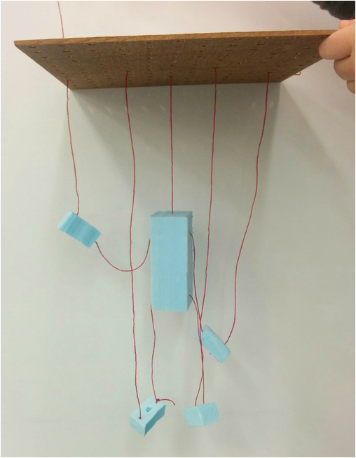
Ultimately, we have decided to return to iterating on our original design. The T-control would have required a lot of space, which contrasted with our goal of containing our system in a nice display case. It also required many degrees of motion that we could barely figure out how to work with our hands, so designing a system that could use the T-control does not make sense.  The mechanical goal for this sprint was to create a puppet that was capable of more humanoid motions than our previous iteration foam and twine puppet. We did quite a bit of research, but found true gold with “How to Make and Operate Marionettes Including Facts About The Pixie Marionettes” by John C. Faustman (PDF found here: http://lcweb2.loc.gov/service/gdc/scd0001/2002/20020129001ma/20020129001ma.pdf) Using this resource, we were able to make our first puppet using a scrap wood, tape, a couple nails and tacks, and several feet of fishing line. The guide was very specific about certain dimensions and lengths, and neglected to mention others, so we took some artistic liberty in our work. We formed the main pieces of the puppet using a band saw, drill, and belt sander to section and shape a scrap piece of 2”x4”. Much to our amusement, we accidentally created several burn lines on the wooden torso piece while we were shaping it—giving it a semblance of abs! We then used artisans tape to make joints for the torso and knees. To simplify the hips we decided that the legs would not be able to move out to the side— as in walking, sitting, and jumping would be possible, but jumping-jacks would not be. This decision allowed us to have a small loop of tape on top of the wooden thigh pieces, which then hung off of two small nails that were carefully placed as the “hips” on the lower torso piece. The arms were a bit more complicated because we needed to consider both the shoulder and elbow motion. We were unwilling to compromise on the motion of the arms, since that is where we saw the most expression happening. We ended up using a loop of fishing line that ran up and over the shoulder as well as through the upper part of the wooden forearm. We modified this by wrapping tape around the loop of fishing line to make it behave more like an arm and isolate the shoulder and elbow. Putting together this marionette took a bit more time than we expected, and the mechanical sub-unit suffered a loss of time due to other class coursework. This resulted in us rather speedily putting together our new marionettes’ stand and rushing through integration. While our stand was not pretty to look at, it handily did its job of holding up the puppet and the 4 motors we needed to implement the motions. The spools, made out of dowel pins and spare gears from the mechanical stockroom, left something to be desired. In sprint 1, we integrated the software and electrical systems by attaching the arduino to both motors through an Adafruit motor shield and uploading our code to the arduino; we then used the button to switch between motions. The motors controlled the motions through a spooling mechanism, where the marionette's limbs were lifted by spooling the control wires (motor running forward), and the limbs were lowered by unspooling the control wires (motor running reverse). In order to produce smooth marionette's motions, we tuned the motor speed and duration of run in the arduino code for that motion.
 Button Circuit Button Circuit For sprint 1, we decided that we would like to program 2 motions for the marionette: left hand lift and right hand wave. Since we were using one Arduino, one Adafruit motorshield, two motors and a button switch, each motor is dedicated to one hand and we switch between the two motions by pressing the button. We set the height that the arms raise by setting the motor speed to be 150 (which ranges from 0 (stopped) to 255 (full speed)) and let it run for 3 seconds. We programmed a one second delay in between raising and lowering arms to get a smoother motion. We also designed a simple circuit for the button to loop through the motions: The direct link to our Arduino file is here: Sprint 1 Button Press Code We are officially beginning our first sprint! First we have to figure out what we want to build. After extensive research and debate, we decided that we wanted to make an actuated marionette that would move in different ways responding to user inputs.
Below is our pre-proposal: At this point our project idea is a dancing marionette. Contained within a decorative case the marionette would be controlled by a set of servos or motors. There are several different iterative steps that we could complete. The most basic form of this project would simply be a marionette that responds to direct commands; raise arm, wave, sit down etc. This would be a hard coded sequence of movements by the marionette (the most basic goal, in case things go wrong). A second iteration would be using a tool such as tracker to match the behavior of the marionette to a predefined video, so that our marionette could dance along with the video; another option would be to have the marionette dance to music at this stage. (this is the ‘middle’ goal that we’d really like to reach). A late iteration, which would be a reach goal, is to set up our marionette in a display case, and use a motion sensor (such as xBox Kinect) to have the marionette mimic a person standing in a specified zone. Ultimately, this system could be displayed in a public space within Olin for the community and guests to enjoy. |
AuthorsSophomore engineers from Olin College of Engineering Archives
December 2015
Categories
All
|
||||||||



 RSS Feed