Minimum Viable Product Vision |
Our mechanical process
After we decided on the hanging balls sculpture (see Sprint 1 in The Process), we decided to make polished and sophisticated gears and pulleys to make the kinetic sculpture more attractive. One of our mechanical goals was to hand make every part of the sculpture. We started by determining the characteristics of the gears based on rotational speeds and the output of our motor. We then CADed the first iteration of gears on Solidworks in order to visualize the positioning. The first CAD was done before the second sprint review to present to Facilities during our meeting with them on installation. We used this base to incrementally tweak our design as we performed tests.
Definitions of the Gear's Characteristics

A gear is mainly characterized by the number of teeth, the pitch diameter and the module of each gear. The module represents the size of the teeth; the bigger the module, the bigger the tooth.
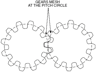
The pitch diameter is a virtual diameter which pre-defines the diametric position on the gear where the teeth perfectly fit in one another based on circular tooth thickness, pressure angle and helix angles are defined. (See illustration on the right. The dotted lines are the circles whose diameters are the pitch diameters.) Since the pitch diameter is a virtual diameter, we could not change this parameter in Solidworks. Therefore, we used the external diameter in the following calculations. It is OK because we do not need to be as precise.
The pitch diameter is a virtual diameter which pre-defines the diametric position on the gear where the teeth perfectly fit in one another based on circular tooth thickness, pressure angle and helix angles are defined. (See illustration on the right. The dotted lines are the circles whose diameters are the pitch diameters.) Since the pitch diameter is a virtual diameter, we could not change this parameter in Solidworks. Therefore, we used the external diameter in the following calculations. It is OK because we do not need to be as precise.
The Calculations

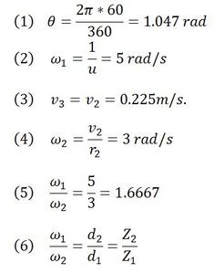
First, we estimated the angular speed of the servo used for the first sprint. According to the datasheet, the speed is u=0.21s/60deg for a voltage of 4.8V. Converting the angle to radians, we have equation (1), where theta is the angle of 60 degrees. Thereby, the angular speed of the servo and the driver gear (the first gear, connected to the motor) is equal to equation (2), where omega 1 is the angular speed of the servo and also the driver gear.
We fixed the velocity of the weight to v3=0.225m/s based on how it should move, taking into account stress on the parts and visual appeal, giving us equation (3), where v2 is the velocity of the driven gear (the second gear, NOT connected to the motor).
In order to calculate the angular speed of the driven gear, we need to choose the driven gear diameter. Once the diameter is defined we have the angular speed of the second gear which is defined in equation (4), where omega 2 is the angular speed of the driven gear. Therefore the ratio between the angular speeds of both gears is equation (5).
Using this value, we can determine the number of teeth and the pitch diameter of each gear. In fact, this ratio equals (6) where Z is the number of teeth and d is the gear’s pitch diameter.
The Adjustments

During the project, we changed the characteristics of the gears and the pulleys several times after testing. We realized the size of the gears was not ideal with the background’s size we chose. Thus, we decided to make the gears bigger. In addition, we changed the thickness of the gears because the interaction between gears was not efficient enough and could create issues for the long-time process. Thicker gears also appear to be more sophisticated. The number of teeth also needed to be adjusted due to limitations with the laser cutter.
The pulleys were also changed for asymmetry in the design. After testing, we decided to make the pulleys thicker for better sliding of the wire by sanding the inside of the pulleys’.
The following equations are what we decided to use for the final values after various iterations.
The pulleys were also changed for asymmetry in the design. After testing, we decided to make the pulleys thicker for better sliding of the wire by sanding the inside of the pulleys’.
The following equations are what we decided to use for the final values after various iterations.
The First Pair of Gears

The equation between the number of teeth and the pitch diameter is the equation (7) where m is the module of the gear which determined the gear’s width. A good value of the module is between 1.5 and 3. First the first pair of gears, we chose a module equal to 3. In fact, these gears are smaller than the second pair of gears so it was better to increase the width.
For the driven gear, we have equation (8). The gears must have the same module to be functional together m1 = m2. For the driver gear, we had to choose a value for the number of teeth and the pitch diameter which an integer number. After some calculations in Excel, we found the equation (9).
For the driven gear, we have equation (8). The gears must have the same module to be functional together m1 = m2. For the driver gear, we had to choose a value for the number of teeth and the pitch diameter which an integer number. After some calculations in Excel, we found the equation (9).
The Second Pair of Gears

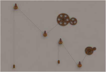
To add a second weight was one of our Sprint 3 goals and part of our MVP. During this part of our project, we actually decided to switch from a servo motor to a stepper motor. As a result, the angular speed does not actually matter. We just had to make sure that the two sets of gears have the same gear ratio. Since we have decided the dimensions of the first pair of gears, we then continued using the same gear ratio with our second set of gears with different dimensions (see equation (10)). This time, we chose a module of 2.5 and a driven gear with a pitch diameter of 20cm. For the driven gear, we have the equation (11). The gears must have the same module to function. Thus m4=m3. Similar to previously, for the driver gear, we need to choose a value for the number of teeth and the pitch diameter that was an integer. After some calculations in Excel, we find equation (12).


