ElectricalLorem
Electrical Engineering Component of Our Project
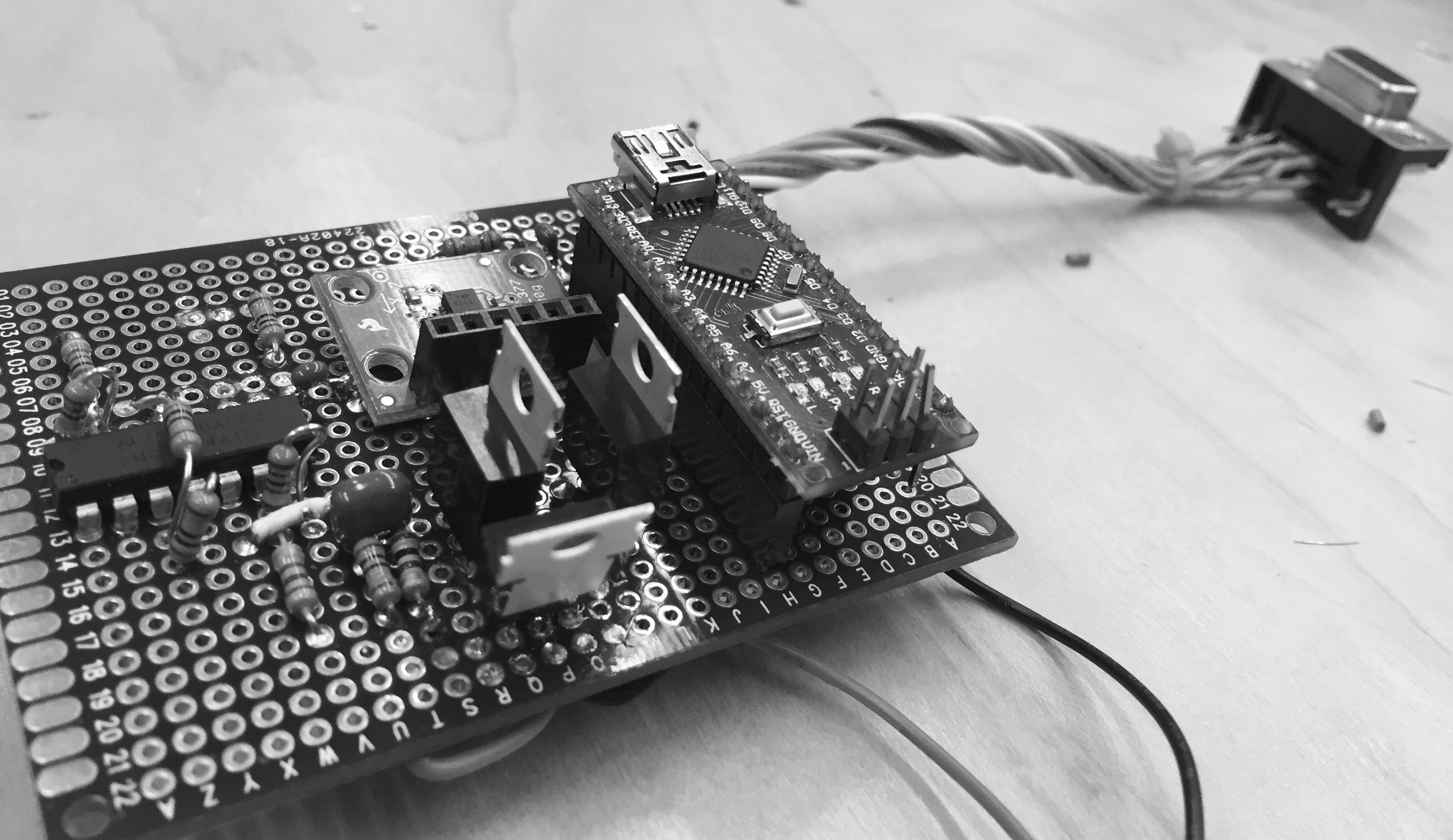
Our ProtoBoard
Sensing Circuit Schematic

Our wearable collects from 3 sensors on the user's body.
- Breathing
- Acceleration
- Proximity
Powering our Components
All of our components are powered by a 7.4V 2200mAh rechargeable lithium polymer battery. A voltage regulator creates a 5V rail from the 7.4V battery, allowing us to power the Arduino, our op-amps, and the servos. To create a 2.5V rail, we use a voltage divider and a buffer. We use the 7.4V from the battery to power our LED components, and use transistors to allow the arduino to control whether current flows from 7.4V through the LEDs to ground.
Breathing
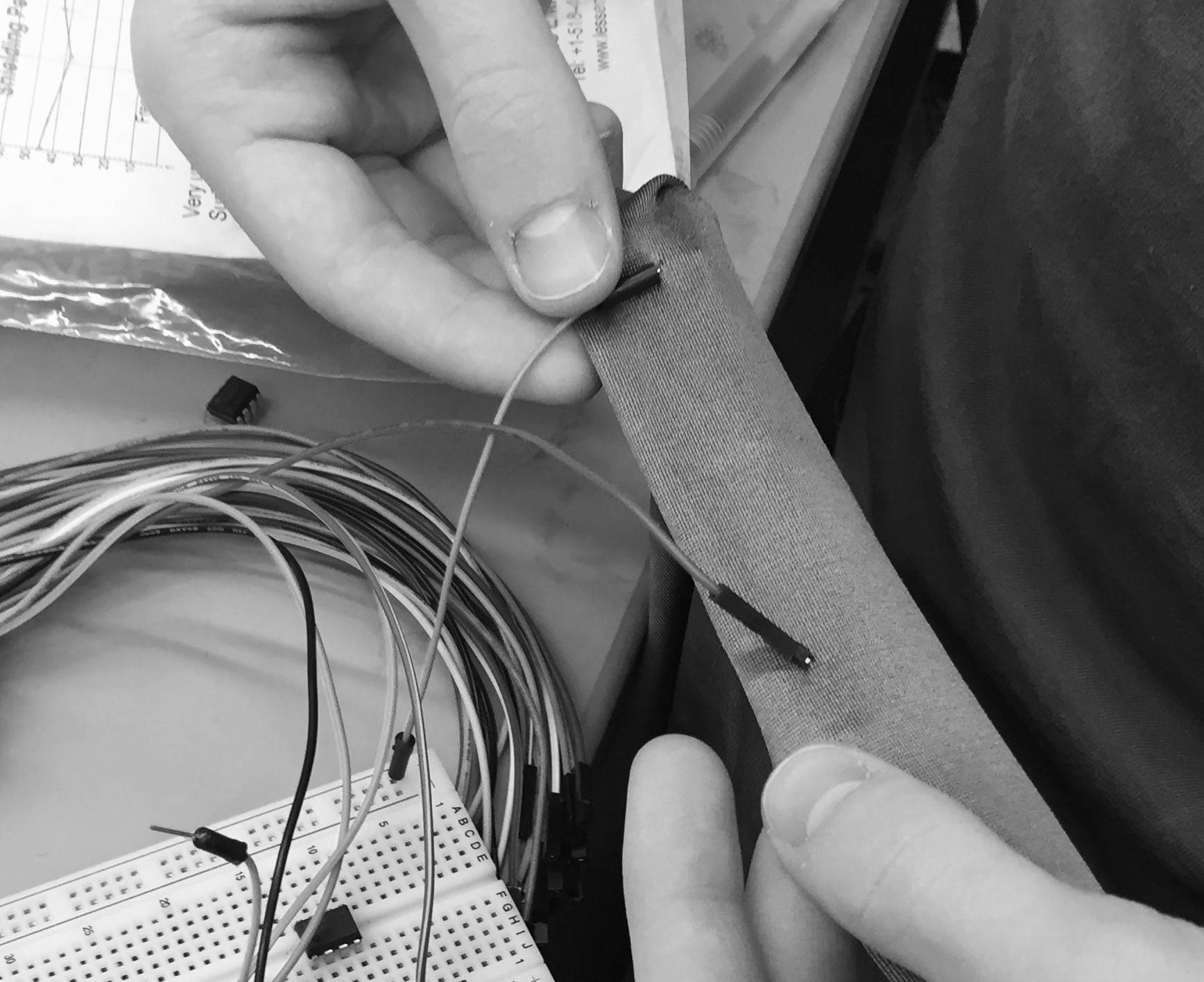
In order to visualize a user's breathing, we created a belt to sense the expanding and contracting of the user's waist. We created an adjustable belt with an elastic piece of conductive fabric in it, shown on the right. The fabric acts as a variable resistor, with a higher resistance when stretched. The fabric is in a voltage divider with a 100Ω resistor. The resistance varies between roughly 8Ω-14Ω, so the voltage at the center of the divider varies between 0.37V and 0.61V. We high pass filter the output of the divider to center the signal around 2.5V, and then we amplify it with a gain of 201, allowing us to detect even the smallest abdominal expansions and contractions. A large gain is necessary because though the resistance can vary from 8Ω-14Ω, this is in ideal conditions, and generally a person breathing will only cause the fabric's resistance to vary by a fraction of its potential.
Acceleration
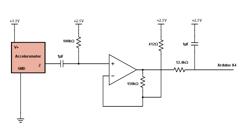
The accerometer circuit is similar to the breathing circuit. We center the signal around 2.5V with a high pass filter and then amplify it with a gain of 389. We need a large gain because a wearable will not experience large accelerations. This amplification introduces noise in the signal, so we low-pass-filter the output of the amplifier.
Breathing Sensing Circuit Schematic

Acceleration
The accerometer circuit is similar to the breathing circuit. We center the signal around 2.5V with a high pass filter and then amplify it with a gain of 389. We need a large gain because a wearable will not experience large accelerations. This amplification introduces noise in the signal, so we low-pass-filter the output of the filter.
Acceleration Sensing Circuit Schematic
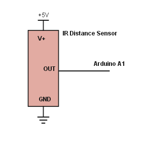
Distance
To sense distance, we used an infrared distance sensor, which can be found here. We wire the IR sensor to power, ground, and an analog input of the arduino. Based on the sensor's voltage, we command the servos to move the spikes back and forth. The larger the sensed voltage, the quicker the spikes move. This sensor is encased in a polyurethane "eye" located on the front of the piece and sense when other people are in close proximity to the wearer.
Distance Sensing Circuit Schematic