Mechanical Deisgn
What is in the Lock, mechanically?
Iteration One
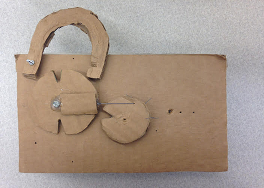
For the first iteration of our project, the goal of the mechanical team was to become familiar with a lock and figure out how to trigger the locking mechanism with some sort of actuator. We researched different types of existing locks and decided to gain inspiration from a combination lock. For this first sprint we created a sketch model of the combination locking system to gain a better understanding. This was made of a ubar, rotating circle, and a lever. When a notch in the circle and the lever were aligned, the ubar would be able to lift up and unlock the system, otherwise the lock would remain locked. We hacked this by integrating a servo and connecting the servo horn to the rotating circle. This created linear actuation. As the servo turned, the rotating circle would move linearly to change the position of the notch.
For our first attempt, we were satisfied with creating a possible locking mechanism that could be powered by an electrical system. Having known nothing about locks before hand, it was interesting to explore this field. At the end of this sprint, we felt comfortable with taking this basic design and modifying it the be implemented in a working prototype.
The Cardboard Iteration
This is the sketch model we created. A servo is under the circle shown on the right and as the circle spins, the left circle moves linearily from left to right.
Iteration Two
Now that we had a basic understanding of simple locks, our goal was to create the concept a fully integrated, functional lock. Last iteration we explored linear actuation with a servo. We liked the movement it created and decided to stick with that idea, but use it in a different way. We also kept the concept of the lock the same. Just like the combination lock, one side of a ubar would slide in and out of the body of the lock. To use this with a bike, the user would wrap a bike chain around their bike and then attach the lock.
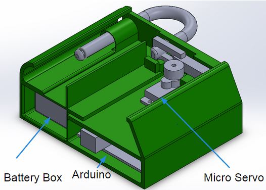
For this iteration, we reduced the amount of parts we had to work with and used a rack and pinion for the linear actuation. The pinion gear was mounted to the servo, and would interact with the rack. Attached to the rack is a bar that would interfere with the ubar. This bar fit into the cut out of the ubar, and would prevent the ubar from being lifted up. To enclose everything, we created a case that securely mounted all the elecrical components, and enclosed them. We 3D printed the case to show how everything would fit into our smart bike lock concept.
Upgrade from Cardboard
Here is the fully integrated lock with the 3D printed case. All components are featured in this CAD model.
Locking Mechanism
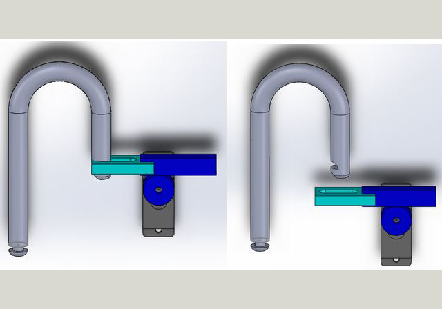
This is the specific locking mechanism used in the second iteration bike lock.
Iteration Three
In this iteration, we wanted to tackle the problem of having the user interact with the app to lock bike. We also wanted to have the lock be attached to a bike chain rather than having the lock and the chain be two separate parts. We redesigned our locking mechanism completely, to interface with the header of a normal bike lock, and got rid of the linear actuation. We now have a male header placed at the end of a chain that inserts into the body of the lock. The user places the lock header into the body, and slides it down to the bottom of the slot. The lock is fully locked at this position. The header slid down past a spring loaded barricade that allows it to slide down, but when the user tries to bring it back up the barricade is in the way. To unlock this, a servo squeezes a spring, moving the barricade out of the way. Then the user can slide the insert back up, and out of the lock body. After a certain amount of time, the servo moves and brings the spring back to equilbrium placing the lock into a locked state.
Stationary Mechanical Aspect
This is where the world will be written out in explanation.
Lock in motion
Here is the lock with cable attached, this is rendered from Solidworks.
Final Iteration
For the final iteration of our bike lock we wanted to refine the design we created in the previous iteration. We were pleased with the locking mechanism and wanted to focus on the integration with electrical system and create a compact case. We really wanted to create a compact box that efficiently utilized each space. We also wanted to keep the user in mind for the design of the box. The final prototype has a very curved shape on one side which fits into the palm of someones hand making it easy to hold. In the end we were pleased with producing a concept of a smart bike lock. Although this lock may not be strong, it can certainly be improved upon to create a more durable lock.
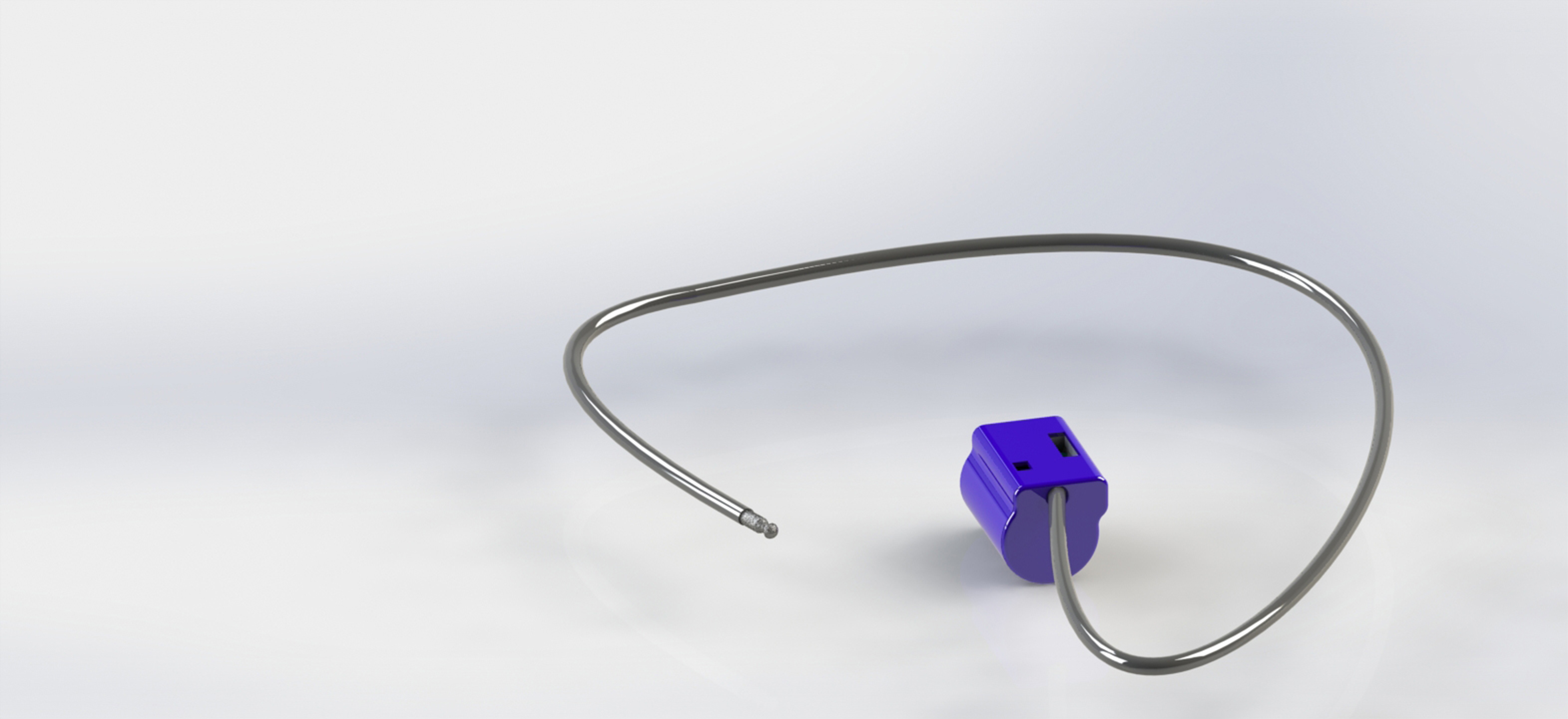
Mechanical
This is a render of the box with it's cable. The box is closed and this is how the lock would look if sitting on a table (not attached to a bike).
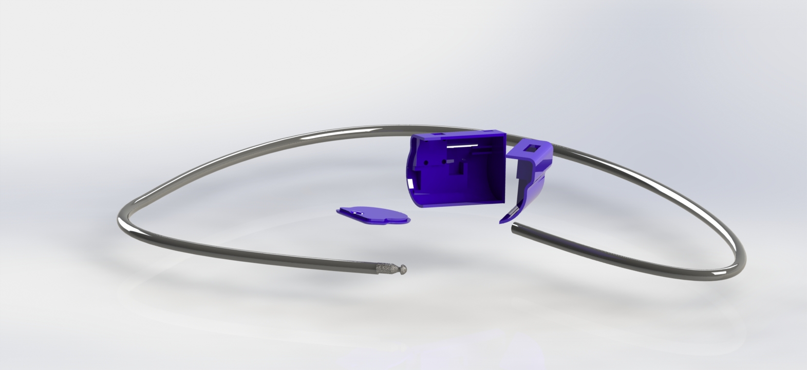
Open Case
This is our lock open with the chain attached. This is the final iteration of the mechanical Deisgn.
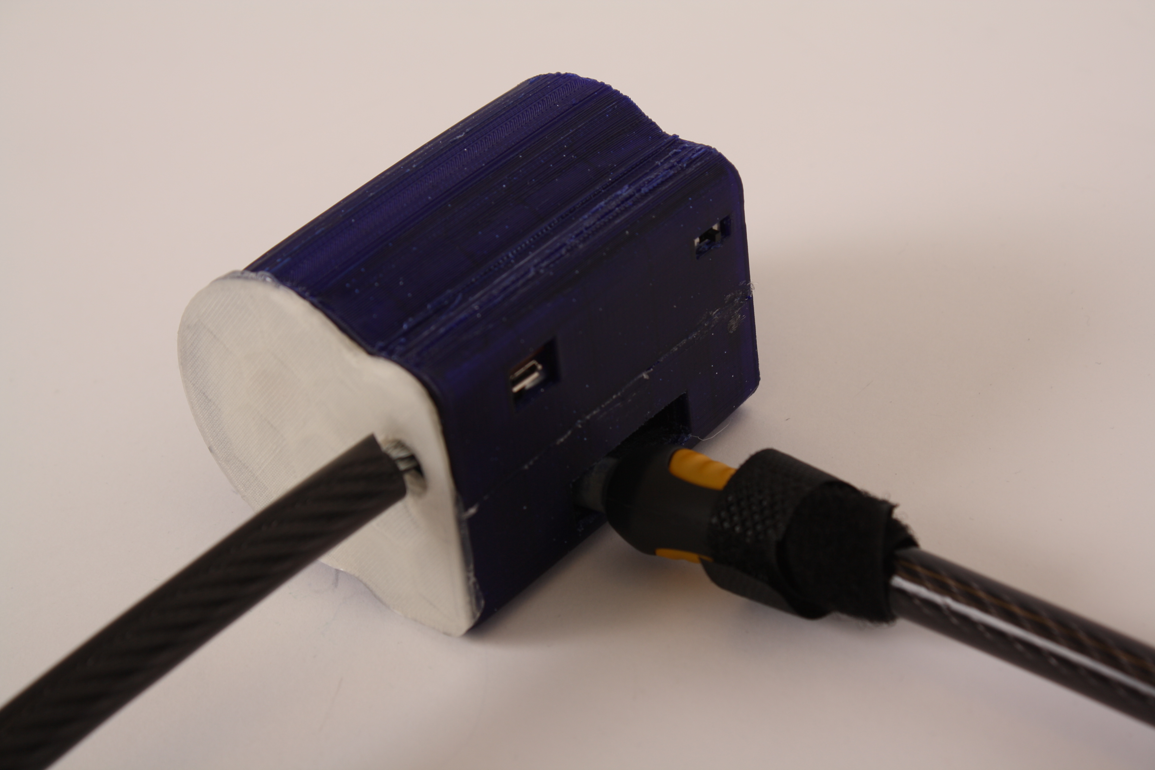
Locked Lock
This is our lock in the closed position.