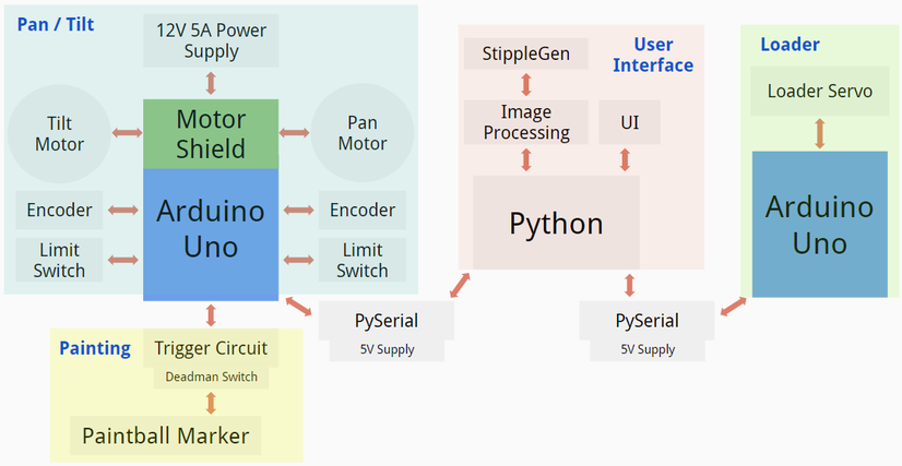
System Diagram
Budget

Pan / Tilt Mechanism
Mechanical
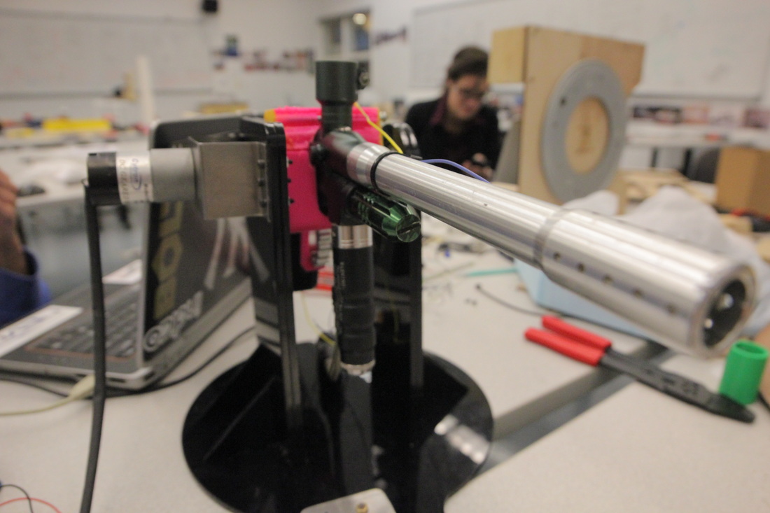
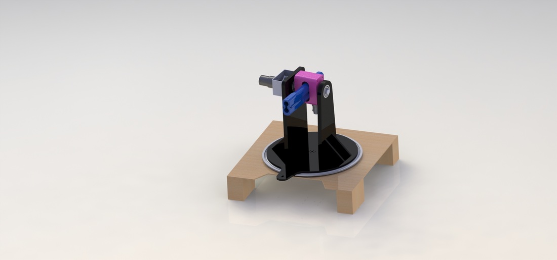
The greatest challenge in designing the pan / tilt mechanism was being able to hold the marker while a large torque is being applied to the system to move the marker. The pan component of the system has a motor driving the base plate from the bottom. The base plate sits on top of a Lazy Susan to allow the system to move easily. The base plate and the supports for the marker are all made out of black acrylic which was manufactured by laser cutting.
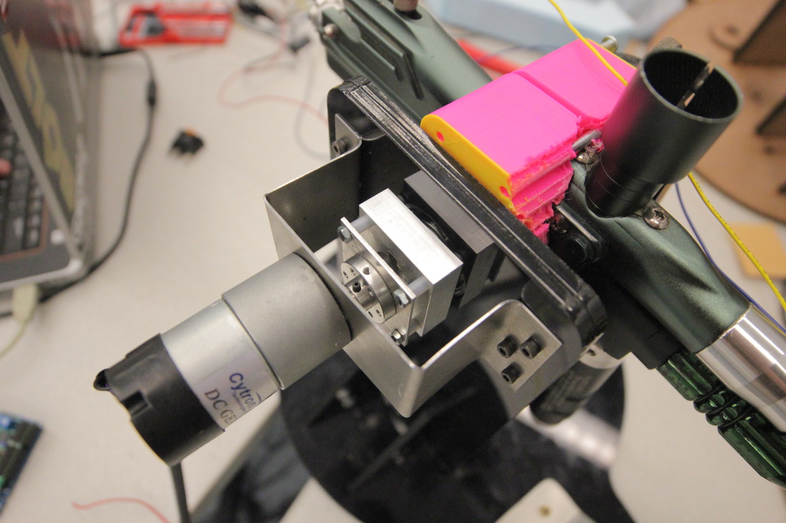
The marker is held by a 3D printed collar with a keyed shaft running through it the collar on either side. The collar and shaft ensure that the marker rotates about its center of mass. The keyed shaft is directly driven by the tilt motor and is securely held in place with aluminum and steel parts.
The marker is held by a 3D printed collar with a keyed shaft running through it the collar on either side. The collar and shaft ensure that the marker rotates about its center of mass. The keyed shaft is directly driven by the tilt motor and is securely held in place with aluminum and steel parts.
Electrical
|
|
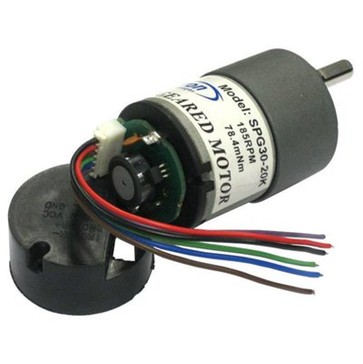
Our electrical system for our pan / tilt mechanism consisted of driving two DC brushed motors with position control. For this, we bought two 12V Cytron technologies DC brushed gear motors with built in quadrature hall effect sensor encoders. One motor has a 270:1 gear ratio and can spin at 12 rpm. It is rated for 1.1W, 410mA, and 1176mN*m torque, with a stall current of 1.8A. We are using this motor to tilt our system, because the high torque will allow us to overcome gravity. The other has a 120:1 gear ratio and spins at 26 rpm. It is rated for 1.1W, 410mA, 588mN*m torque, with a stall current of 1.8A. We use this motor to pan our system.
Both motors come with 5V quadrature hall effect sensors to use as encoders. These have 3 shafts per rear shaft revolution, which means that the pan and tilt motor encoders have 810 and 360 counts per main shaft revolution, which gives us a lot of resolution for position control.
Both motors come with 5V quadrature hall effect sensors to use as encoders. These have 3 shafts per rear shaft revolution, which means that the pan and tilt motor encoders have 810 and 360 counts per main shaft revolution, which gives us a lot of resolution for position control.
The state diagram above explains how the encoders work. Using quadrature hall effect sensors allows us to have two encoder signals. Due to the switching between high and low, and the one time step offset between the two encoders, it is possible to determine direction, in addition to change in position. Every time we sense a change on either encoder line, we can check the state of the other encoder to determine if it was a clockwise or counterclockwise change, and increment the angle of the system accordingly. The Arduino documentation has a nice article on using encoders like this one.
With precise position measurements, we could use a PI controller, similar to what we built in lab 3, to control our pan and tilt motors. We read some literature on tuning PID controllers to assist with this process. When driving the motors without a load, we found that proportional control was more than sufficient to control them accurately. We may need to add integral control for more precise control when we tune the control algorithm once the motors and mounted on the pan / tilt mechanism. The large size of the paintball splats (about 2x2 in), however, makes precise control less important.
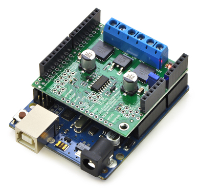
The Adafruit motor shields we used in lab 3 have a maximum output current of 1.2A per channel, so we decided to buy a higher power motor shield. We ended up using the Pololu MC33926 motor shield, which has two motor lines. This shield can provide up to 2.5A to each motor continuously, meaning that it will work for us even if we are continuously pushing stall current on our motors. We would recommend this shield to future PoE teams, because all of Pololu's equipment is very well documented.
In addition to our motors, we used two limit switches for zeroing of our pan and tilt mechanisms. We mounted both limit switches at theoretical mechanical stops of our system, in order to zero the positions of both motors before we began to control them. We also mounted (and powered) a 5V laser to the end of our paintball marker in order to clearly see where the marker was pointing at all times.
With precise position measurements, we could use a PI controller, similar to what we built in lab 3, to control our pan and tilt motors. We read some literature on tuning PID controllers to assist with this process. When driving the motors without a load, we found that proportional control was more than sufficient to control them accurately. We may need to add integral control for more precise control when we tune the control algorithm once the motors and mounted on the pan / tilt mechanism. The large size of the paintball splats (about 2x2 in), however, makes precise control less important.
The Adafruit motor shields we used in lab 3 have a maximum output current of 1.2A per channel, so we decided to buy a higher power motor shield. We ended up using the Pololu MC33926 motor shield, which has two motor lines. This shield can provide up to 2.5A to each motor continuously, meaning that it will work for us even if we are continuously pushing stall current on our motors. We would recommend this shield to future PoE teams, because all of Pololu's equipment is very well documented.
In addition to our motors, we used two limit switches for zeroing of our pan and tilt mechanisms. We mounted both limit switches at theoretical mechanical stops of our system, in order to zero the positions of both motors before we began to control them. We also mounted (and powered) a 5V laser to the end of our paintball marker in order to clearly see where the marker was pointing at all times.
Firmware
We used an Arduino Uno in combination with the Pololu motor shield to drive our motors. We ended up using almost all of the pins on the Arduino, due to the internal pin mappings the motor shield required to drive the motors. In addition to motor lines M1 and M2 on the motor shield, it required pins 4, 7, 8, 9, 10, and 12 for PWM and error pins. Our limit switches, which are mentioned in the electrical system, are used in the initialization sequence that is in the setup() function of our code.
In writing our firmware, we used pins 2 and 3 as interrupt handlers, because of the fast operation of our encoders. We attached the encoder lines of our pan motor to pins 2 and 5, and of our tilt motor to pins 3 and 6. Whenever either interrupt was triggered on a CHANGE of pin 2 or 3, we would increment a counter up or down by comparing pin 2 to pin 5 or pin 3 to pin 6 to determine if the motor was moving clockwise or counterclockwise.
This Arduino script communicates with Python through pySerial to receive pan and tilt angles from a Python script. This script also handles the trigger of our marker.
Paintball Loader

Mechanical
The mechanical system is simpler than it appears. Three different colors of paintballs, each in its own tube, sit on top of a rotating plate with a singular hole large enough for one paintball. Additionally, a plate below the rotating plate confines the movement. While the bottom plate also has holes large enough for a paintball to fall through, these holes are offset from where the balls drop into the top plate so that there is never a complete opening straight from the tubes to the paintball marker.
When the top plate rotates, one ball can drop into the singular slot in the plate. Only one ball can submerge into the plate due to its thickness. The rotating plate then rotates away from where the balls drop until an opening in the bottom plate. The singular ball submerged in the top rotating plate can then continue falling through the bottom plate toward its destination while the top rotating plate rotates back toward a tube to load an additional ball.
When the top plate rotates, one ball can drop into the singular slot in the plate. Only one ball can submerge into the plate due to its thickness. The rotating plate then rotates away from where the balls drop until an opening in the bottom plate. The singular ball submerged in the top rotating plate can then continue falling through the bottom plate toward its destination while the top rotating plate rotates back toward a tube to load an additional ball.
Electrical
The electrical system of our loader is relatively simple, as it only uses a hobby servo to load a paintball of a specific color, and then drop it through a funnel to the paintball marker. For simplicity, we load all paintballs of a single color before moving on to the next color. One problem with our design is that the servo we are using is only capable of about 200 degrees of movement, so it is not fully compatible with our loading system, which requires more than 240 degrees of movement. As a result, we are only able to load two colors of paintballs. In the future, we would like to resolve this problem by purchasing a better servo.
Firmware
The firmware to control the servo ended up being more complicated than we envisioned, due to the way it uses Arduino's built in 16 bit timers. The Arduino Uno has only one 16 bit timer (Timer1), which is attached to pins 9 and 10. These timers are the way the Arduino uses its digital pins for pulse width modulation, which is the way that the Arduino controls a Servo. The problem we ran into was that our motor shield requires the operation of pins 9 and 10 to control the PWM signal of our motors. As a result, we observed very odd behavior when we tried to use our Servo on the same Arduino as the motor shield. We found a third party library that made the Arduino use another one of its timers to control the Servo (the Arduino Uno also has two 8 bit timers, termed Timer0 and Timer1). The problem was that this timer used pin 3, which we needed as an interrupt handler. We could have written our own modified Servo library to use the final timer, but decided instead to use a second Arduino Uno.
The only added complexity with adding a second Arduino was that we had to communicate with two Arduino Unos from a single Python script. We handled this by simply opening two serial objects from the Python script to talk to both Arduinos. One useful resource that explains the Arduino timers in more detail is provided here. The Arduino script we used to control the servo and listen to serial is in our GitHub repository.
The only added complexity with adding a second Arduino was that we had to communicate with two Arduino Unos from a single Python script. We handled this by simply opening two serial objects from the Python script to talk to both Arduinos. One useful resource that explains the Arduino timers in more detail is provided here. The Arduino script we used to control the servo and listen to serial is in our GitHub repository.
Trigger
Electrical
We bought a paintball marker with an electrical trigger mechanism, which made our triggering easier. At a high level, the way the internal circuitry of the marker works is that pressing the trigger shorts two wires, which causes a solenoid to click. As a result, we designed a basic circuit to short those two wires whenever we want to trigger the marker.
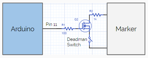
A circuit diagram of this system is shown above. We used the 2n7000 MOSFET to control the trigger. Essentially, whenever we set pin 11 HIGH, the Vgs of the transistor is high enough to close the transistor, which shorts the drain and source. By attaching the two lines from the marker together, we then click the solenoid. We added a resistor from the high side marker line to the drain of the FET, to limit the current going through the FET so that we do not exceed its maximum current.
We also added a deadman switch between the source of the FET and the low side marker line for more safety. This way, even sending a HIGH signal to the gate of the FET does not trigger the marker unless the deadman switch is being held down. This is because the low side marker line is left floating unless the switch is pressed.
We also added a deadman switch between the source of the FET and the low side marker line for more safety. This way, even sending a HIGH signal to the gate of the FET does not trigger the marker unless the deadman switch is being held down. This is because the low side marker line is left floating unless the switch is pressed.
Firmware
We control our marker from the same Arduino script as we control our pan / tilt mechanism. The script uses timing using millis() to call the fire() function whenever pan and tilt angles are communicated to the Arduino over serial. Each time it does this, it waits five seconds before calling the function, to give the system sufficient time to pan and tilt and load the paintball. The fire() function simply sets pin 11 HIGH for a second before turning it LOW again.
Software System
Our software system is written in Python, and communicates with our Arduino over pySerial. The most important aspect of this system is to do image processing. At a high level, it can take in an image, process it to a series of Cartesian coordinates, and then convert those coordinates to angle measures using basic trigonometry. We convert from Cartesian to spherical by taking the arc tangent of each of the Cartesian coordinates, and correcting for any off centering of our system.
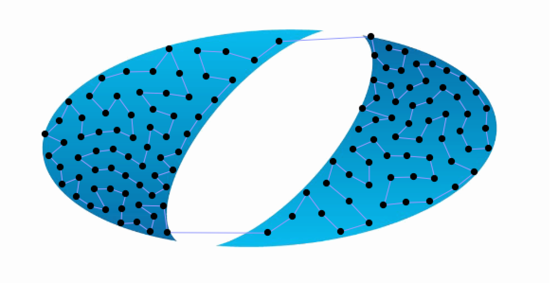
For image processing, we are using an external software platform called StippleGen, which takes in an image and uses Voronoi diagrams to convert it to a series of points ordered using a shortest path algorithm. It then outputs the path in svg format. The image below shows an example of using the software to recreate an image of a heart.
For image processing, we are using an external software platform called StippleGen, which takes in an image and uses Voronoi diagrams to convert it to a series of points ordered using a shortest path algorithm. It then outputs the path in svg format. The image below shows an example of using the software to recreate an image of a heart.


Our Python script uses a few external libraries. In addition to the basic math and time libraries, we use serial to communicate with our Arduinos. We also use bs4 (beautiful soup) for parsing the svgs from StippleGen. Finally, we use matplotlib to make basic plots for the purpose of debugging. Our python script is located here.
All of our code is located in our GitHub repository.