
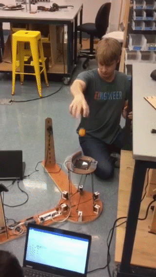
Bounce is a take on the classic robotics problem of the ball-bouncing robot. Our approach uses a Stewart platform to continually position a speaker under a ping pong ball as directed by a laptop connected to a pair of webcams. When the ball falls on the speaker, a laser plane-break detection system triggers it to hit the ball back into the air. Thus our robot is able to bounce a ping pong ball indefinitely — we have recorded it bouncing a ball for over 2 hours before it stopped because of lighting conditions.
The Project


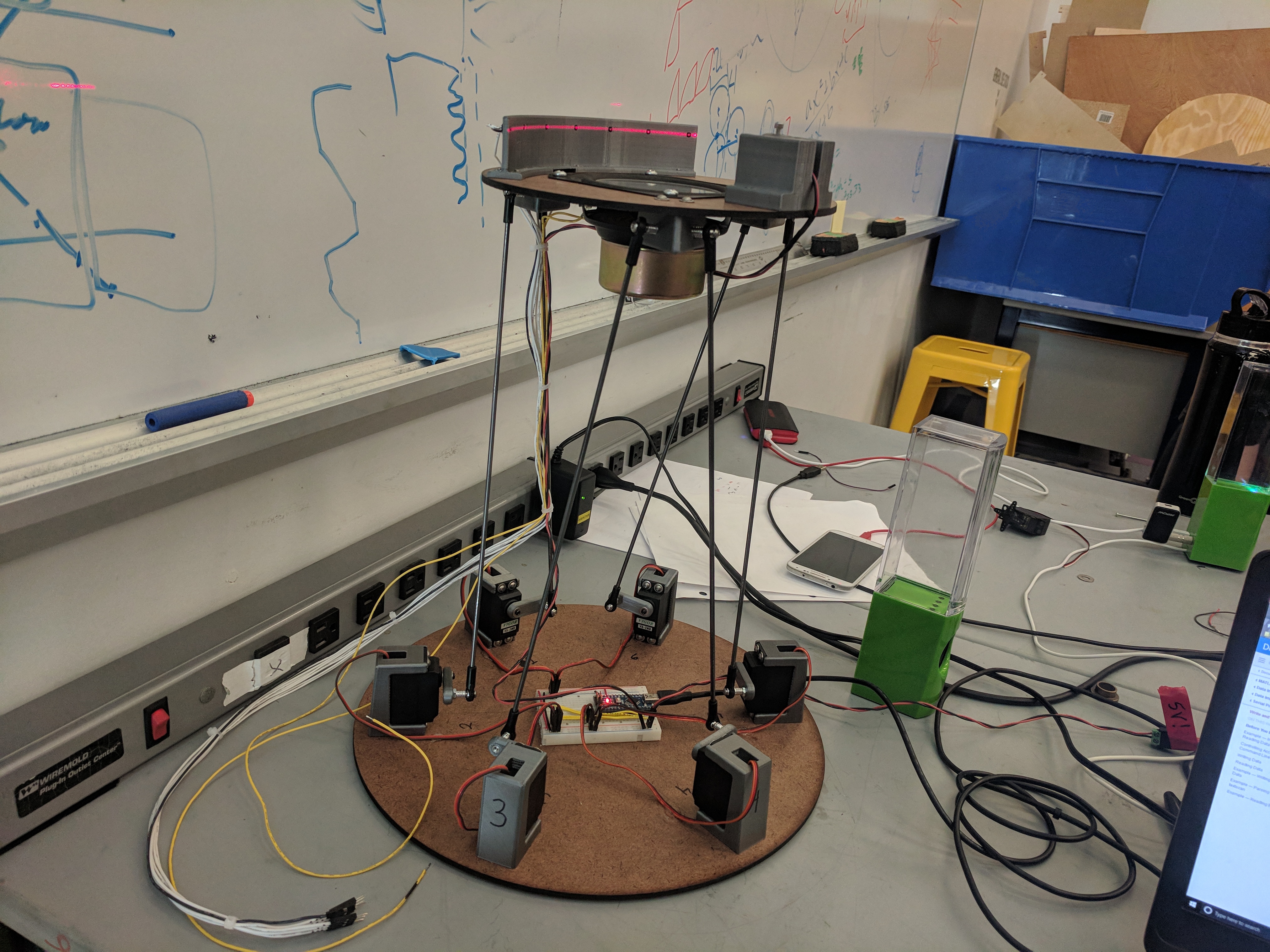
The Stewart Platform
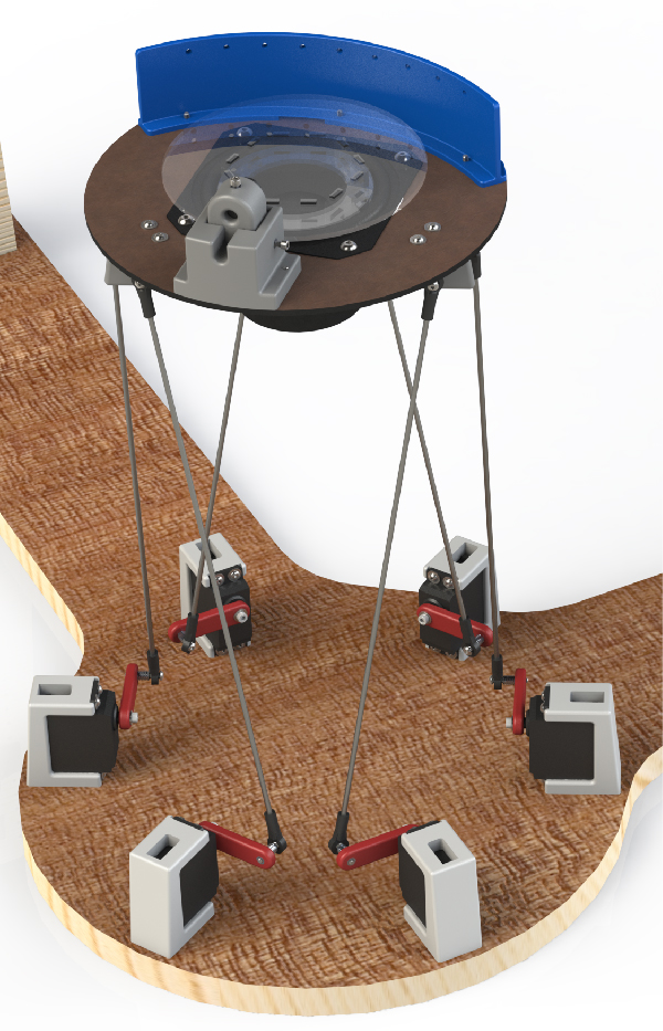
The Stewart platform is the central mechanical component of our project. It is what holds and positions the speaker to hit the ping pong ball. A Stewart platform is a unique mechanical structure that uses six actuators acting in parallel to move a platform, giving the platform six degrees of freedom (x, y, z, yaw, pitch, roll). For our application, we are using only four degrees of freedom (x, y, pitch, roll), but we decided that this structure would be simpler, more robust, and more interesting to build than a four DoF platform, such as an x-y gantry with a two-axis gimbal on it. We also wrote software that is able to position the platform in all six axes
Geometry
The actuation distance, connecting rod length, platform size, base size, and distribution pattern of connecting rods on the top and bottom all affect the performance and range of the platform. To design a platform that would have the characteristics we needed, we started by writing a Stewart platform model in Mathematica. After playing with the model for a while, we decided on these dimensions and built a prototype platform. The dimensions of our final platform are given below:
- Servo Horn Length: 1.375 inches
- Connecting Rod Length: 12.625 inches
- Top Connection Point Diameter: 6.92 inches
- Top Connection Point Separation: 20.45 degrees
- Bottom Connection Point Diameter: 7.375 inches
- Bottom Connection Point Separation: 60 degrees
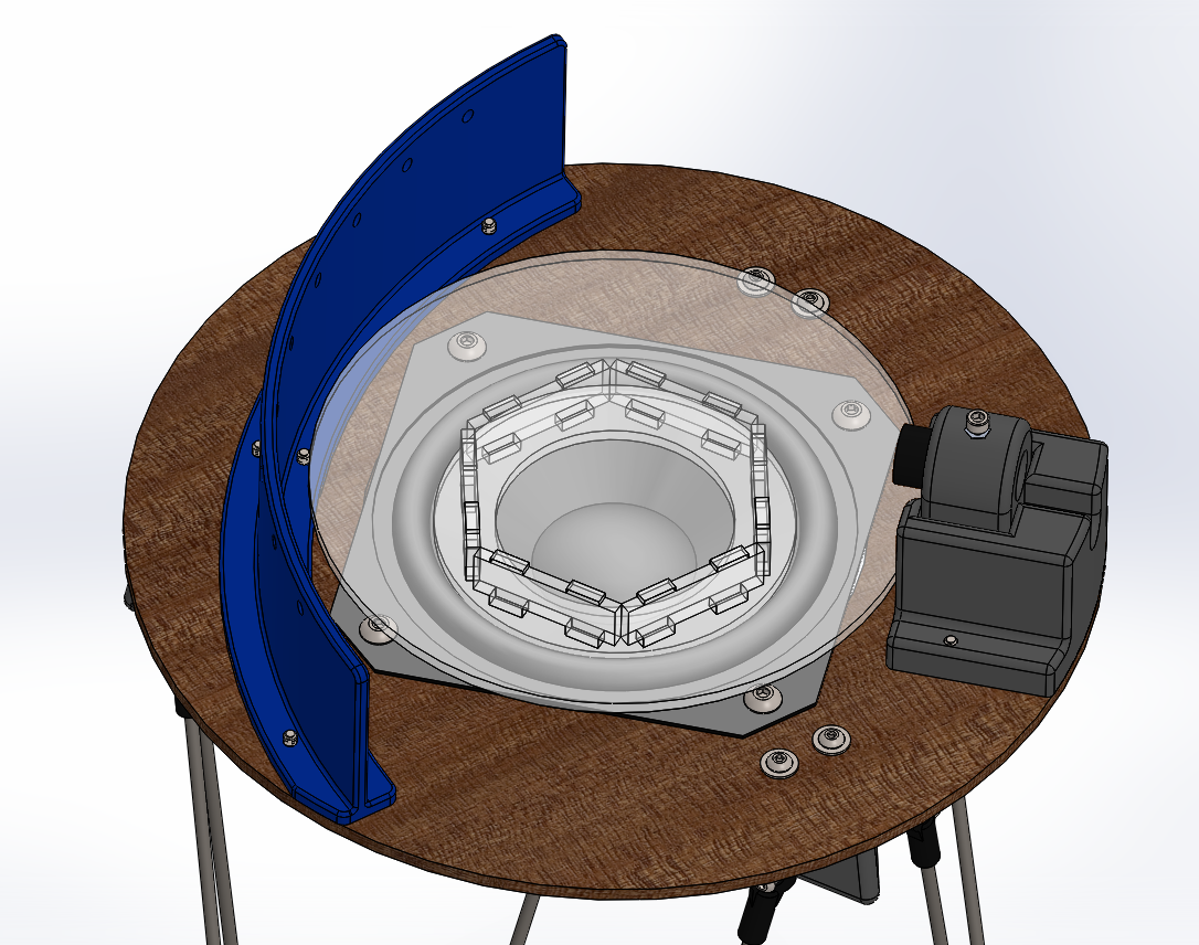
The Hitting Mechanism
In order to keep the ball in the air, we needed to impart a bit of energy to it with each bounce. Using the z-axis motion of the Stewart platform would not have worked for several reasons: it simply doesn’t move fast enough, use of the z-axis limits the x-y-pitch-roll range of the platform, and the use of rotational actuators for linear motion would require us to individually control the speed of the motors through the stroke in order to get linear motion of the platform. For these reasons, we decided from the beginning to use a speaker to hit the ball. This works well because speakers can be used as relatively light weight, high speed linear actuators.
 Because of the short stroke of the speaker, the timing is vital to getting a consistent bounce. For this reason we use a separate Arduino whose only job is to fire the speaker at the right time. If our servo controller Arduino has recieved a command in the last second, the speaker is primed and ready to hit. Otherwise, the speaker returns to the neutral position. The computer vision is not precise or consistent enough to send fire time to the speaker, so we built a plane-break sensor and positioned it above the plate.
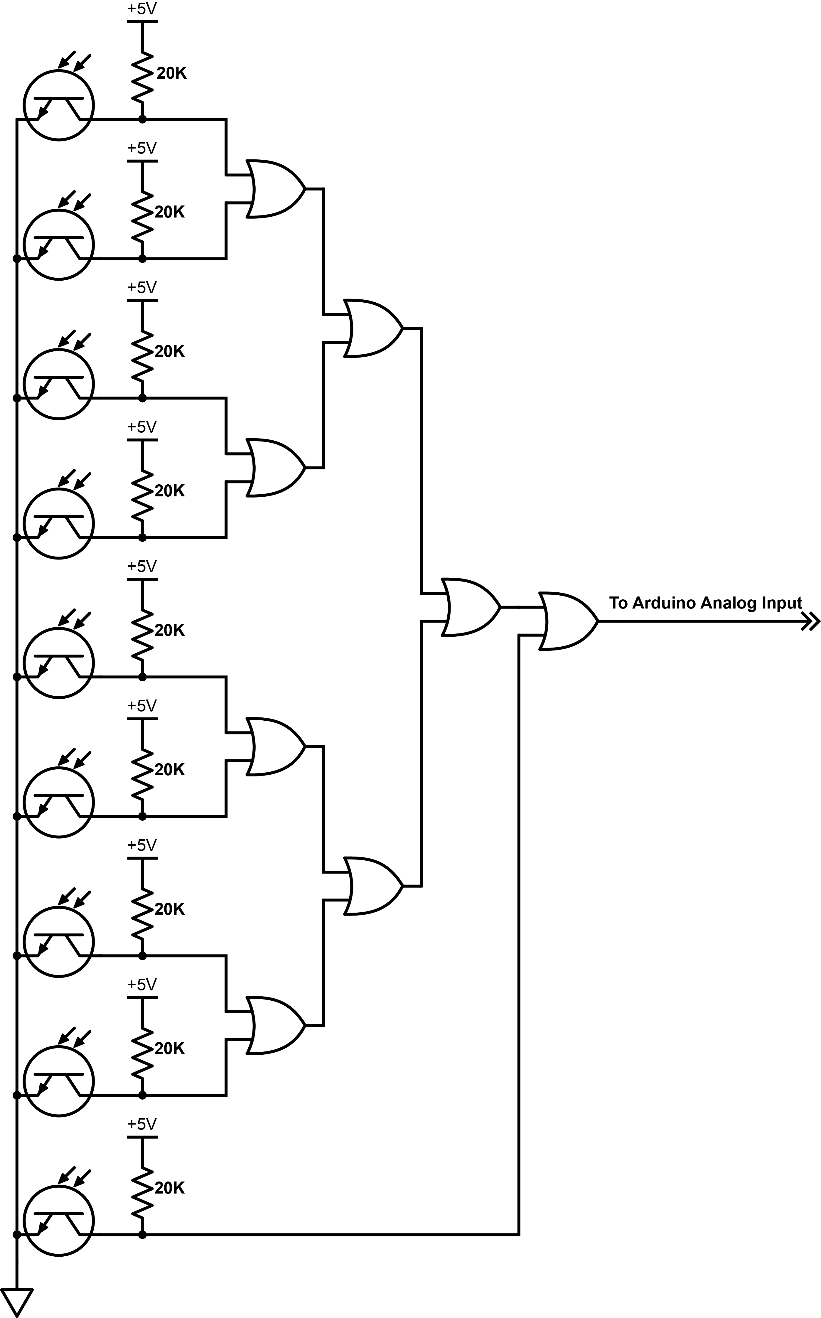
The plane break sensor consists of a red line laser that shines in a 90 degree arc across the hitting platform. The laser is mounted such that it can be adjusted precisely to hit the array of nine visible light phototransistors on the other side of the platform. The light from the laser saturates the transistors, so interference from visible light is not a problem unless it is extremely bright. To avoid using lots of pins on the Arduino, we chained the sensors together through a tree of eight OR gates. The transistor output is low when saturated and goes high when the beam is broken, so the Arduino receives a high signal when one or more of the sensors is blocked from the laser by the ball, and it knows to trigger the speaker to fire. See diagram on the right.
After struggling for a long time to get the system to work for more than three or so bounces, we increased the size of the hitting plate glued to the speaker, and the system started working immediately. We had not tried this earlier because we assumed that the size and weight of the mechanical structure required would slow the speaker down too much and cause it to hit the ball erratically. We found that in fact, while it does slow down the speaker, its mass increases the consistency of the hits, and its size allows for occasional off-center hits to be recovered.
Computer Vision and Platform Positioning
All of our CV and platform positioning software is written in Python and runs on a laptop. We locate the ball in each frame by using openCV to select a mostly circular contour matching the color of the ping pong ball, and finding the center of the largest enclosing circle of that contour. We then use NumPy to find the epipolar ray from each camera that the ball must lie along, and estimate the position of the ball as the point closest to both of those rays.
We continuously update the platform to try to stay under the ball, and scale its tilt according to the position and velocity of the ball. We estimate the velocity of the ball as the change in position divided by the change in time since it entered the cameras’ field of view. The farther the ball is from the center of the platform’s range in each direction, the more the platform tilts to correct. Likewise, the faster the ball is moving in the x-y plane, the more the platform tilts to correct.
We calculate the position that the servos must go to in order to move the platform to the desired location using a numeric optimization from SciPy. We know where the platform should be, and we know how long the theoretical legs of the platform must be to reach that position, so we use the Brenth root finding method to find servo angles where the distances from the pivot points of the servo horns to the corresponding points on the platform are equal to the target leg lengths. Finally, we pack those angles into a byte array using the bitstring library, and send them to the servo controller Arduino over serial. Then all the Arduino has to do is unpack the byte array and send the servo angles to the appropriate servos.
Camera Calibration

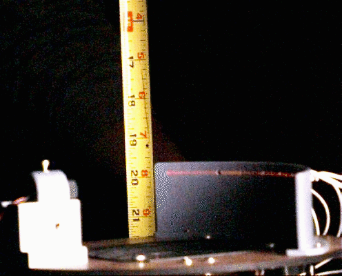
To calibrate the cameras we constructed a plumb bob with a ping pong ball on the string, as shown in the image above. We used the plumb bob to establish that our platform could move horizontally with extremely high accuracy. By positioning the platform at various known horizontal positions, and the ping pong ball on the plumb bob at various heights above the center of the platform, we found the ball’s image coordinates for both cameras at 316 points. We then built a mathematical model of the cameras, and performed a least squares optimization on the error of the model to find the correct parameters for the model. These parameters included the cameras’ positions, angles, focal lengths, and frame centers. These parameters were vital to finding the correct epipolar rays when locating the ball in 3D space.
All our software and firmware can be found hereThe Process
Sprint 1
For sprint one, we focused on refining our idea and then making a proof-of-concept for the hitting mechanism. Early on we gained confidence in the Stewart platform, but we were unsure about how we would actually hit the ball. After some testing, we decided a speaker would be the best way to go; it has the right combination of qualities for our use – quick response time, relatively low weight, and the ability to impart a significant impulse.
To test our idea for the sensing system, we grabbed a few IR reflectance sensors that we had used on a previous lab, constrained the motion of the ball, and proved that the circuit could respond fast enough to hit the falling ball.

Sprint 2
For sprint two, our goal was to build the Stewart platform, put together a first pass of the laser sensing system, and get computer vision controls working in one dimension. For CV and mechanical, the sprint went without a hitch. By sprint two review day we were demoing our Stewart platform control with a laptop webcam and a ping pong ball in the air. The laser sensing system, however, gave us some difficulty. We had bought phototransistors whose sensitivity was centered around 930nm, which we thought would solve any problems with ambient light interference, but they turned out to not be sensitive enough to detect the line laser we specced. This left us sensorless and without an operational hitting mechanism at the end of sprint two, and with long shipping times on new sensors, little time to get the sensing working for the end of the next sprint.
Sprint 3
By the end of sprint three we were supposed to have the MVP completed. While we waited for our new phototransistors to arrive we tuned the computer vision and stewart platform controls, fixing as many bugs as possible without a hitting mechanism in place. At the end of week one of the two-week sprint, the package arrived and we got to work building the laser sensing system. Fortunately, ambient light interference turned out to not be an issue, and we were able to construct the circuit to signal our Arduino when one of the sensors was blocked.
With all of the systems in place, the focus of the sprint turned to getting everything to work in unison. Although we were able to present our MVP for the sprint review, Bounce could not keep a ball in the air for more than a few hits, and our work was cut out for us for the next sprint.
Sprint 4
Sprint four was an all-or-nothing sprint for our team. The individual components of our project were all finished in sprint 3, so we were left to figure out how to get the ball bouncing consistently. We started by making small improvements wherever possible – we changed out our motor controller, increased the length of the servo horns, calibrated the computer vision, and ran endless tests. In the end, significantly upping the size of the hitting plate made the difference, and just like that, it started working!

Bill of Materials
| Part | Qty Purchased | Qty in Project | Amount Paid for Item | Hypothetical Cost |
|---|---|---|---|---|
| Digital Servos | 7 | 6 | $94.99 | 81.42 |
| Line Laser | 1 | 1 | $24.95 | $24.95 |
| Rod Ends | 40 | 12 | $22.00 | $11.00 |
| Visible Phototransistors | 10 | 9 | $15.09 | $15.09 |
| Spring Wire Rods | 10 | 6 | $7.09 | $7.09 |
| Webcams | 2 | 2 | $46.73 | $46.73 |
| Speakers | 0 | 1 | $0.00 | $8.71 |
| Motor Driver | 2 | 1 | $8.99 | $4.50 |
| Arduino Nanos | 0 | 2 | $0.00 | $7.93 |
| Breadboards | 0 | 2 | $0.00 | $6.99 |
| 5V 3A Power Supply | 0 | 1 | $0.00 | $7.59 |
| 9V 1A Power Supply | 0 | 1 | $0.00 | $7.59 |
| Quad OR Gate | 0 | 2 | $0.00 | $1.10 |
| #4-40x3/4" screws | 0 | < 1 pack | $0.00 | $4.03 |
| #4-40 x 1/2" screws | 0 | < 1 pack | $0.00 | $3.12 |
| #4 washers | 0 | < 1 pack | $0.00 | $3.23 |
| #4-40 threaded inserts | 0 | < 1 pack | $0.00 | $12.25 |
| 3D printer filament | 0 | < 170g | $0.00 | $5.00 |
| Scrap stock (3/4" & 1/4" ply, 1/8" acrylic) | 0 | $0.00 | $0.00 | |
| Point Lasers | 10 | 0 | $5.99 | $0.00 |
| IR Phototransistors | 20 | 0 | $6.00 | $0.00 |
| Solenoids | 3 | 0 | $21.33 | $0.00 |
Estimated Project Cost: $260.71
Total Amount Actually Spent: $253.16
The Team
Rowan Sharman
Rowan is a sophomore at Olin College of Engineering and is majoring in Mechanical Engineering. He wanted to practice creating robust and flexible designs for iterative prototyping during this project. He did design work on most of the mechanical components, lots of manufacturing, and circuit design and building. His favorite machine shop tool is the automatic center punch. Contact
Henry Rachootin
Henry is a sophomore at Olin College of Engineering and is majoring in Engineering with a Concentration in Math. Having had some experience with firmware, he wanted to keep his embedded C skills from getting rusty. As a math major, he wanted to do some mathematical modeling for this project. With these goals in mind he wrote the firmware for this project, and constructed the mathematical models for the Stewart platform and the cameras. His favorite machine shop tool is the surface table. Contact

Onur Talu
Onur is a sophomore at Olin College of Engineering and is majoring in Mechanical Engineering. Going into this project, he wanted to get more experience with mechanical design and integration; therefore he worked on the design and manufacture of sensor and adjustable laser mounts, top and bottom platforms, along with designing for a system that would have used solenoids as actuators instead of a speaker. His favorite machine shop tool is Gojo 0955 Natural Orange Pumice Hand Cleaner™. Contact

Jonathan Jacobs
Jonathan is a sophomore at Olin College of Engineering and is pursuing a major in Engineering with a Concentration in Mathematical Modeling. For this project his learning goals were to understand the basics of electrical engineering, improve his documentation skills, and learn web development. Jonathan worked primarily on the presentations, documentation, and website for the project, making significant progress in the latter two learning goals. He also performed analysis with the high speed camera and aided the other members of the team when necessary. His favorite machine shop tool is a dull wood rasp. Contact
Toby Shapinsky
Toby is a sophomore at Olin College of Engineering majoring in Engineering with a Concentration in Computing. For this project he wanted to gain experience in writing realtime robotic computer vision systems. He has worked with computer vision systems in the past but wanted to get better at writing one from the ground up. His favorite machine shop tool is needle and escapement files. Contact