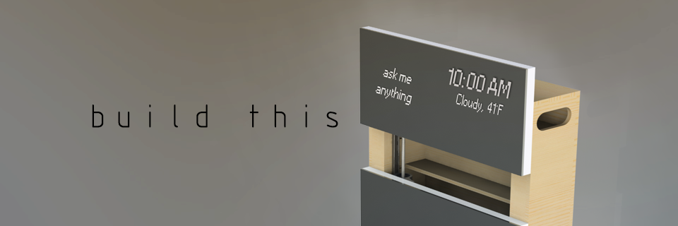
The future is in front of you.
A POE 2016 Team Design/Build Project
Overview and Integration
spec·ter
ˈspektər/
noun: spectre
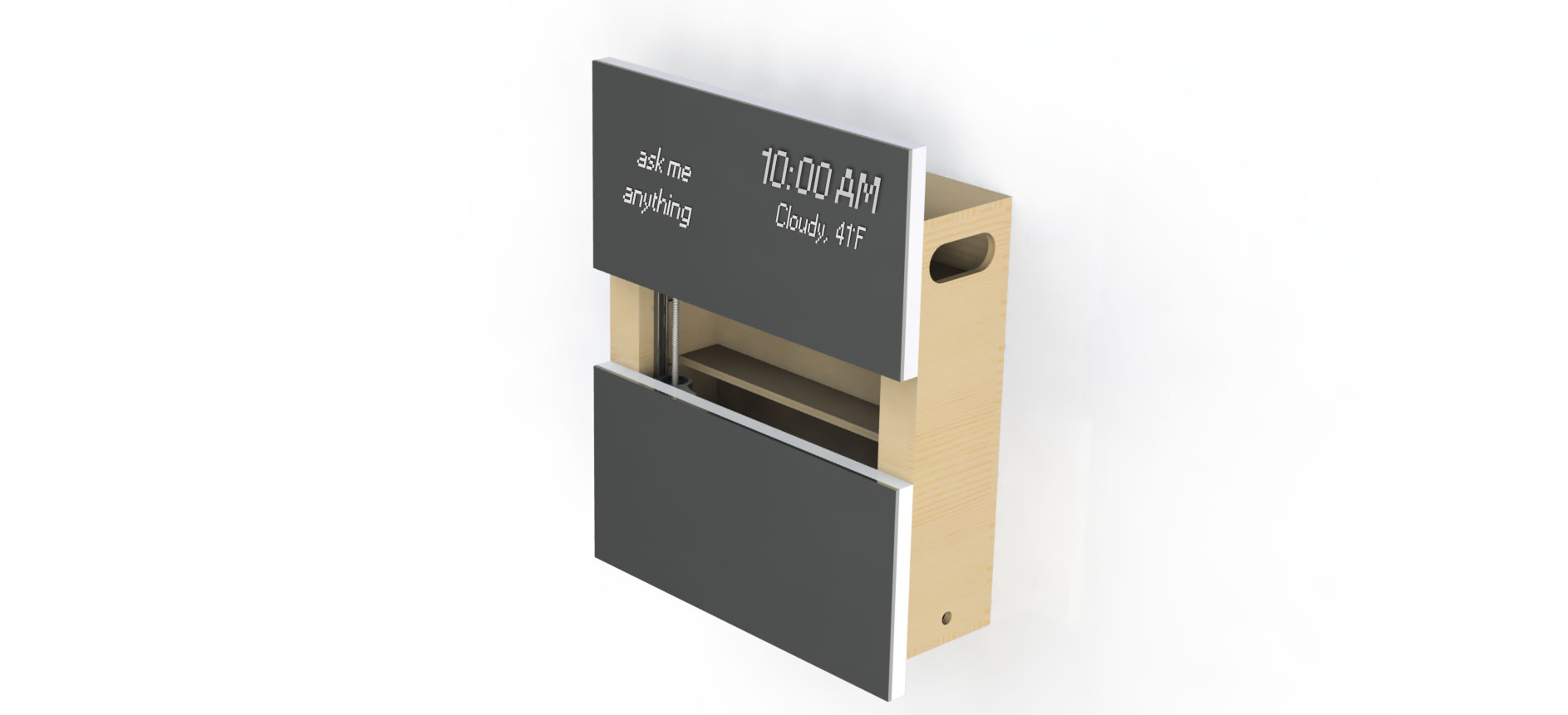
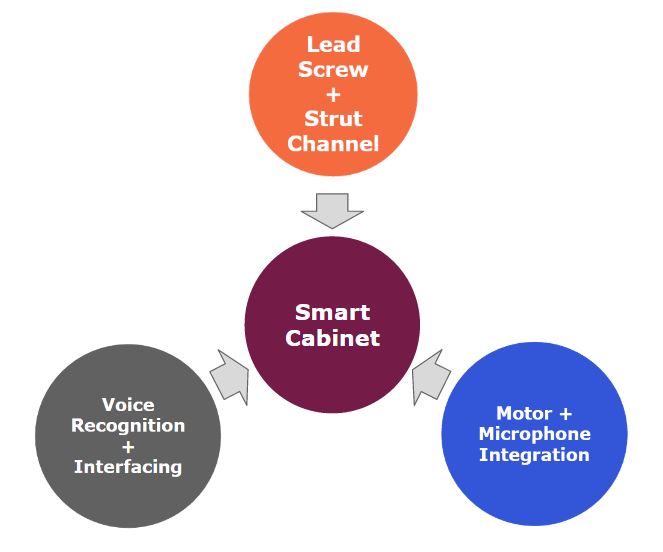
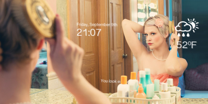
Spectre is an interactive, voice controlled smart mirror and cabinet system. Spectre provides information, entertainment, and convenience for users in the most personal of spaces -- the bathroom. Spectre has dual mirrors that open and close vertically, thereby giving users access to the shelf they want without the need to lift a single finger.
Demonstration Videos of Spectre:
DESIGN PROCESS
WHY SPECTRE? IDEATION.
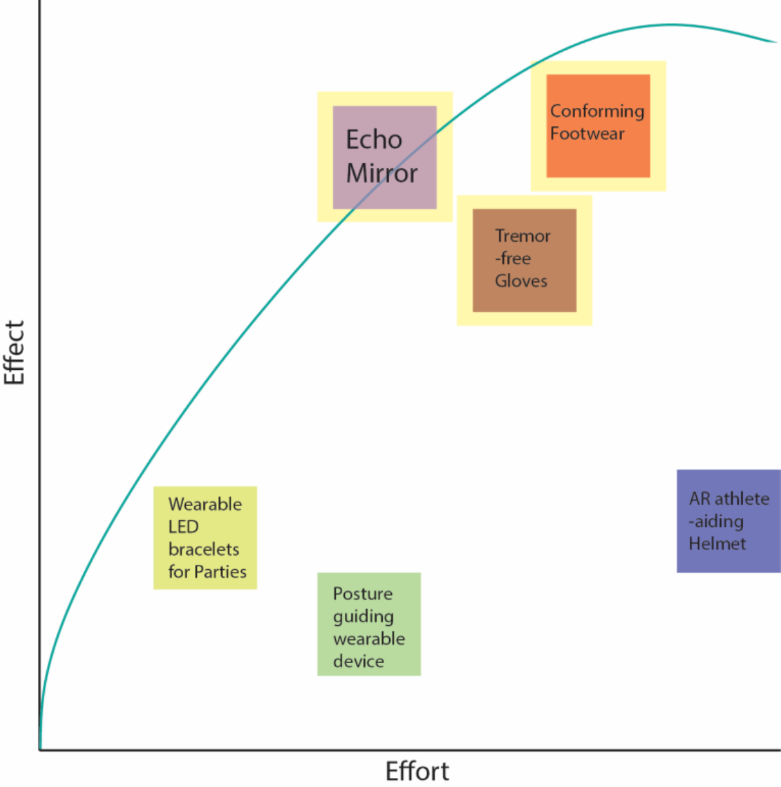
From “wearables” to “interactive hardware” to “Spectre,” our team’s ideation process was quite special. First, we started with an exercise called the “Effort vs Effect graph,” where all ideas are plotted on the graph according to their effort to effect ratio. Our goal was to choose three ideas that required a good amount of effort and output a relatively high effect. The three we ended up choosing is highlighted in yellow.
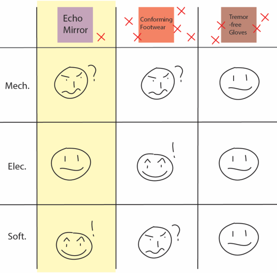
With the three chosen ideas, we did an exercise more specific to our team goal, which was to have equal mechanical, software, and electrical components throughout the project. As you can see, we scored each idea for the three components using happy, mellow, and sad faces.
Finally, we did an elimination exercise, where each teammate put X’s on two of the ideas they wanted to eliminate. The exercises left us with one idea : the Echo Mirror. With the addition of automated dual-mirror feature as the mechanical component, we finalized on the automated smart mirror, Spectre.
INSPIRATION.
Clean and high quality
Personal Assistant
Smudge-free Mirror
Do It Yourself
Materials Breakdown
Item
Quantity
Total Cost to Us
Total Typical Cost
Purchased From
12'' by 24'' 2-way see-through acrylic mirror
2
$53.98
$50.00
Amazon
12VDC Motors
2
$53.34
$50.00
Amazon
Raspberry Pi 2 Model B
1
$0.00
$42
Amazon
Raspberry Pi Power Supply
1
$0
$8
Amazon
7" LCD Display for Raspberry Pi
2
$71.96
$70
Amazon
USB Microphone
1
$9.78
$10
Amazon
Wifi dongle for Raspberry Pi
1
$8.99
$10.00
Amazon
12V LCD Power Supply
2
$15.98
$15
Amazon
3 feet HDMI cable
1
$4.99
$5.00
Amazon
3D printing filament
N/A
$0
$4
Hatchbox
Velcro
N/A
$0
$5.00
Anywhere
2' by 2' 15/32" Plywood
1
$8.00
$8.00
Home Depot
4' by 4' 15/32" Plywood
1
$13.00
$13.00
Home Depot
1/2" Pink Insulation Foam
1
$4.99
$5.00
Home Depot
Extra Low-Profile Strut Channel
2
$14.30
$14.30
McMaster
General Purpose Fully Threaded Rod
2
$17.14
$17.14
McMaster
Right-Hand General Purpose Hex Nut, 3/8"
2
$5.80
$5.80
McMaster
Building a mechanical housing for Spectre
Getting the components ready
ShopBot the cabinet parts and the foam frame.
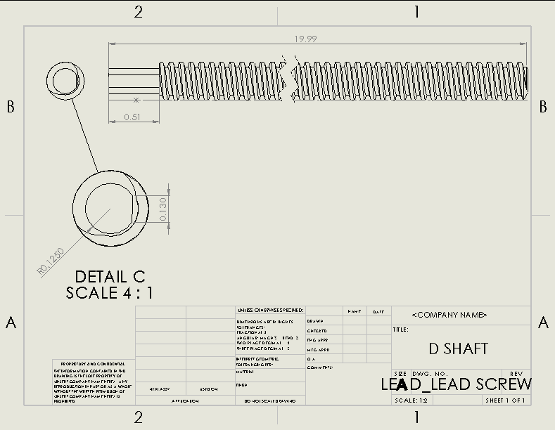
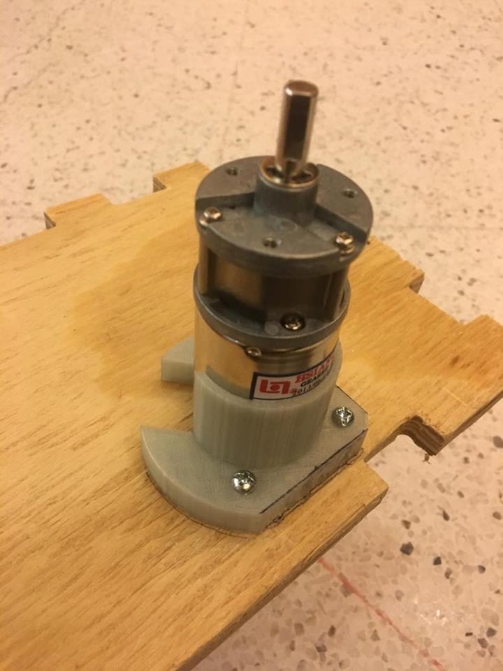
Mill and lathe the leadscrew D-shaft.
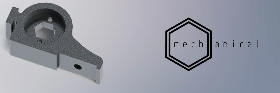
3D print the shaft connector, hex-nut socket, and motor bracket
Laser cut the U supports.
Assembling the components
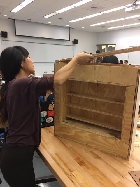
Partially assemble the cabinet
Integrate motor brackets, motors, hex-nut sockets, strut channels, and leadscrews on to the cabinet assembly.
Assemble the Raspberry Pi screens, motor-board and foam frame
Wiring electronics
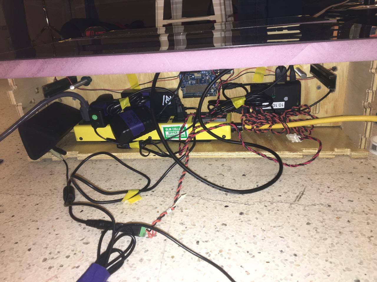
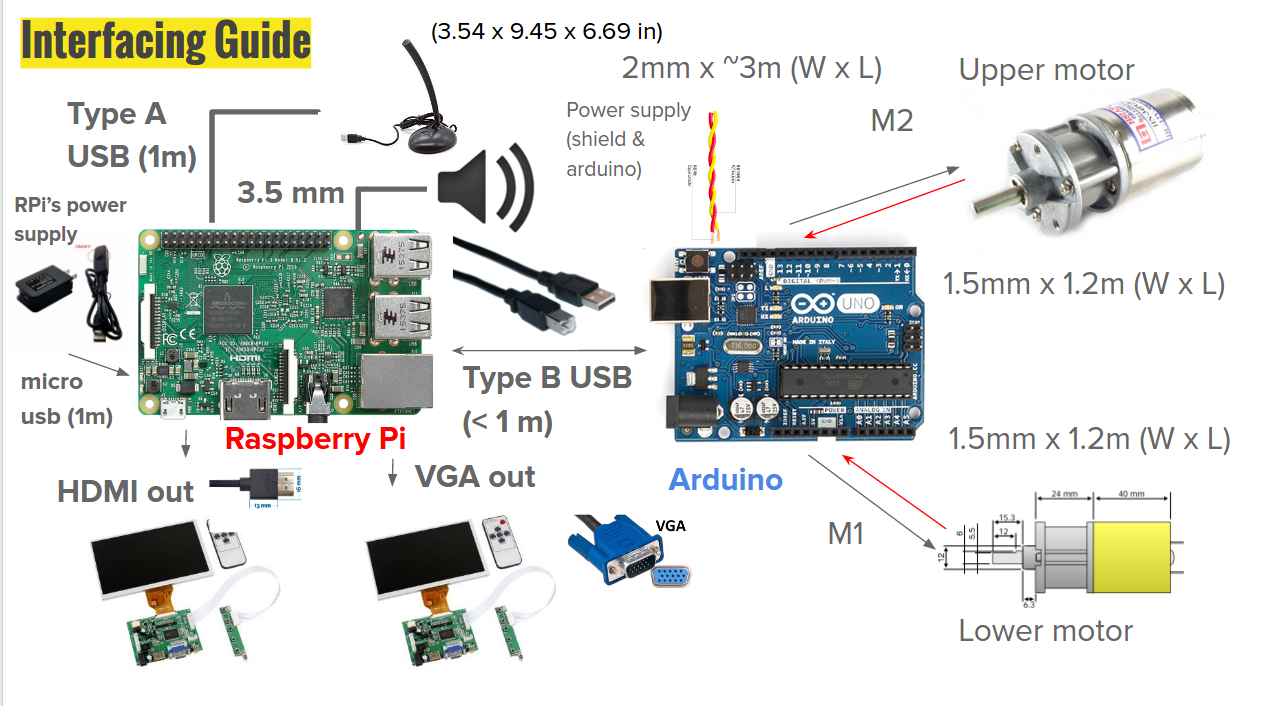
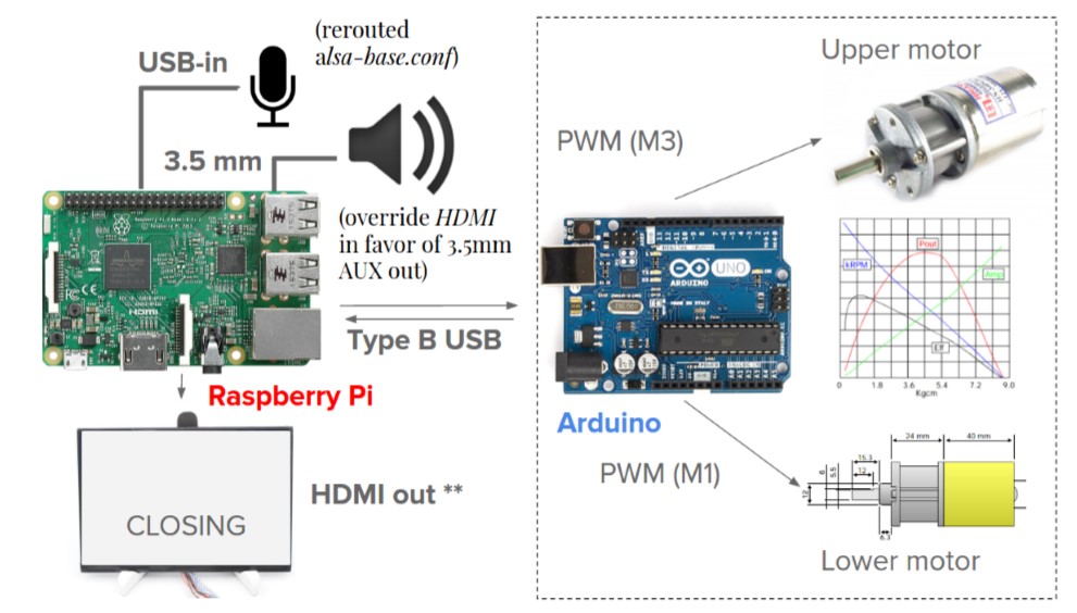
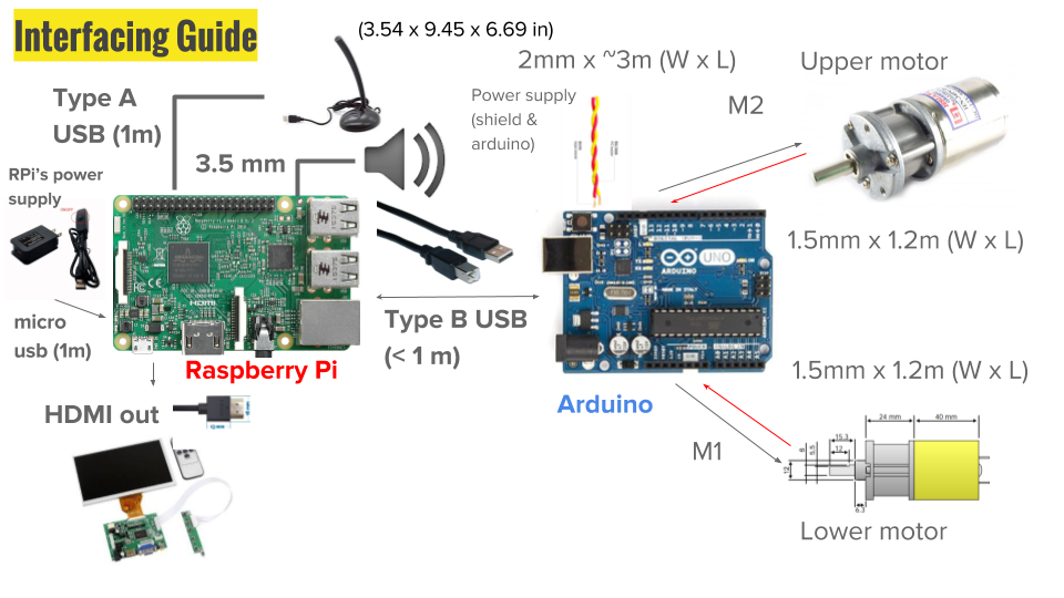
Quick Peek:
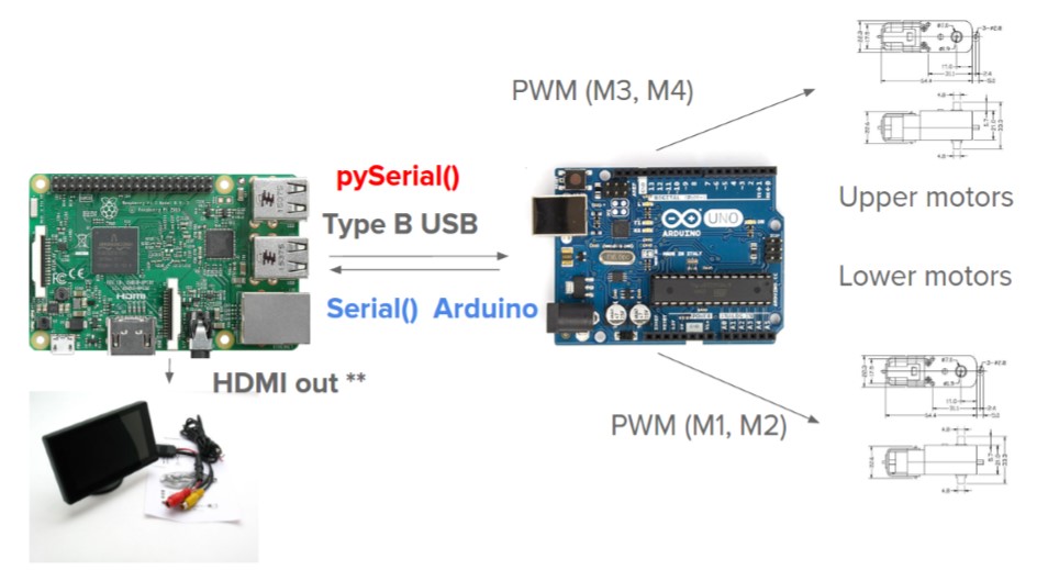
The electronics behind Spectre is composed of two major parts - an Arduino side, and a Raspberry Pi side. They are connected via a serial interface (covered later), which allows them to transmit key information to mechanize the entire structure.
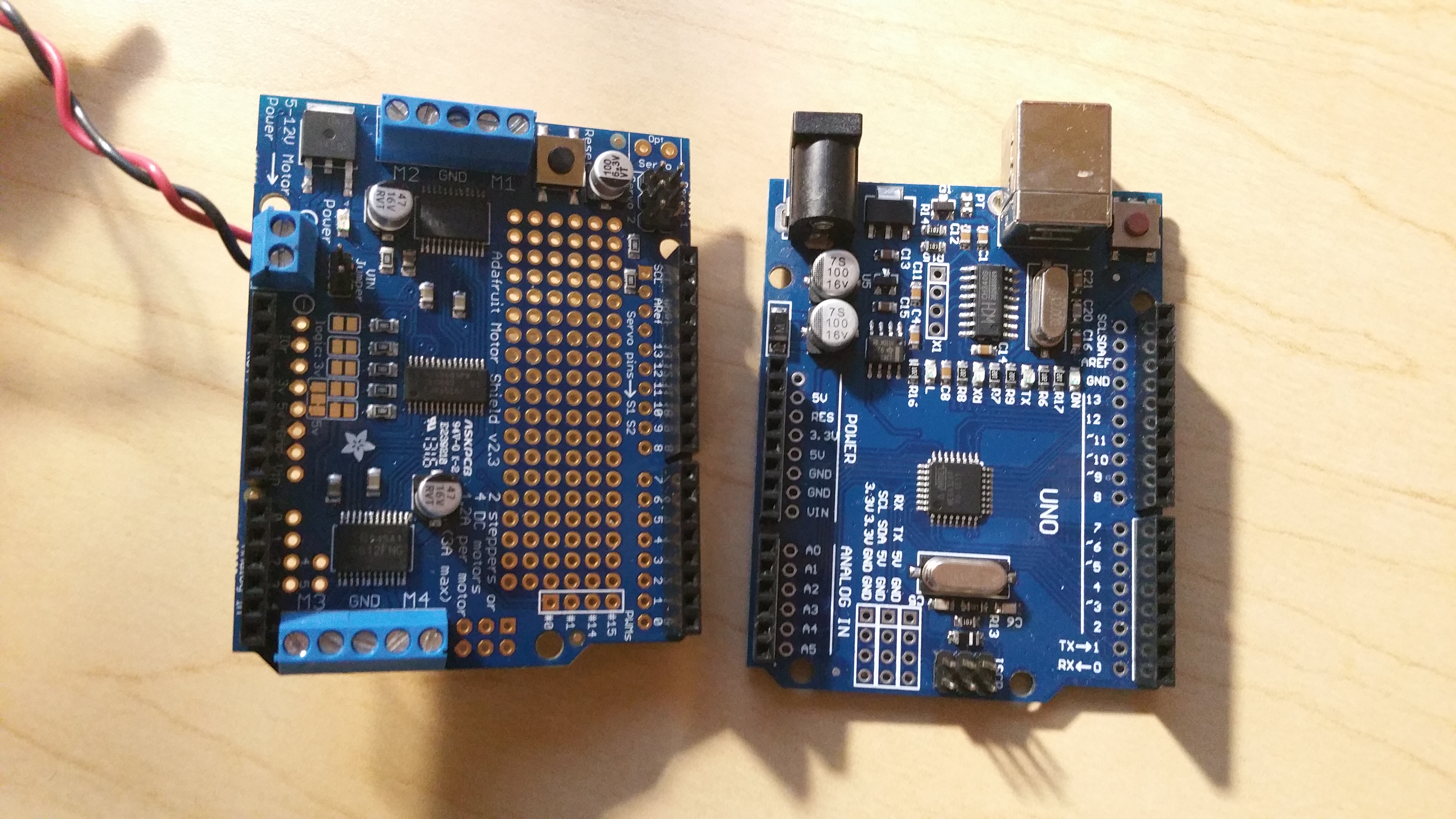
Arduino End
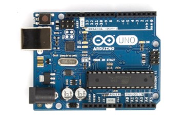
Step 1: Connect the Motor Shield to the Arduino
Align the Adafruit Motor Shield to the I/O pins of the Arduino Uno R3. If done correctly, the motor shield should stack nicely atop of the Arduino’s female heads.
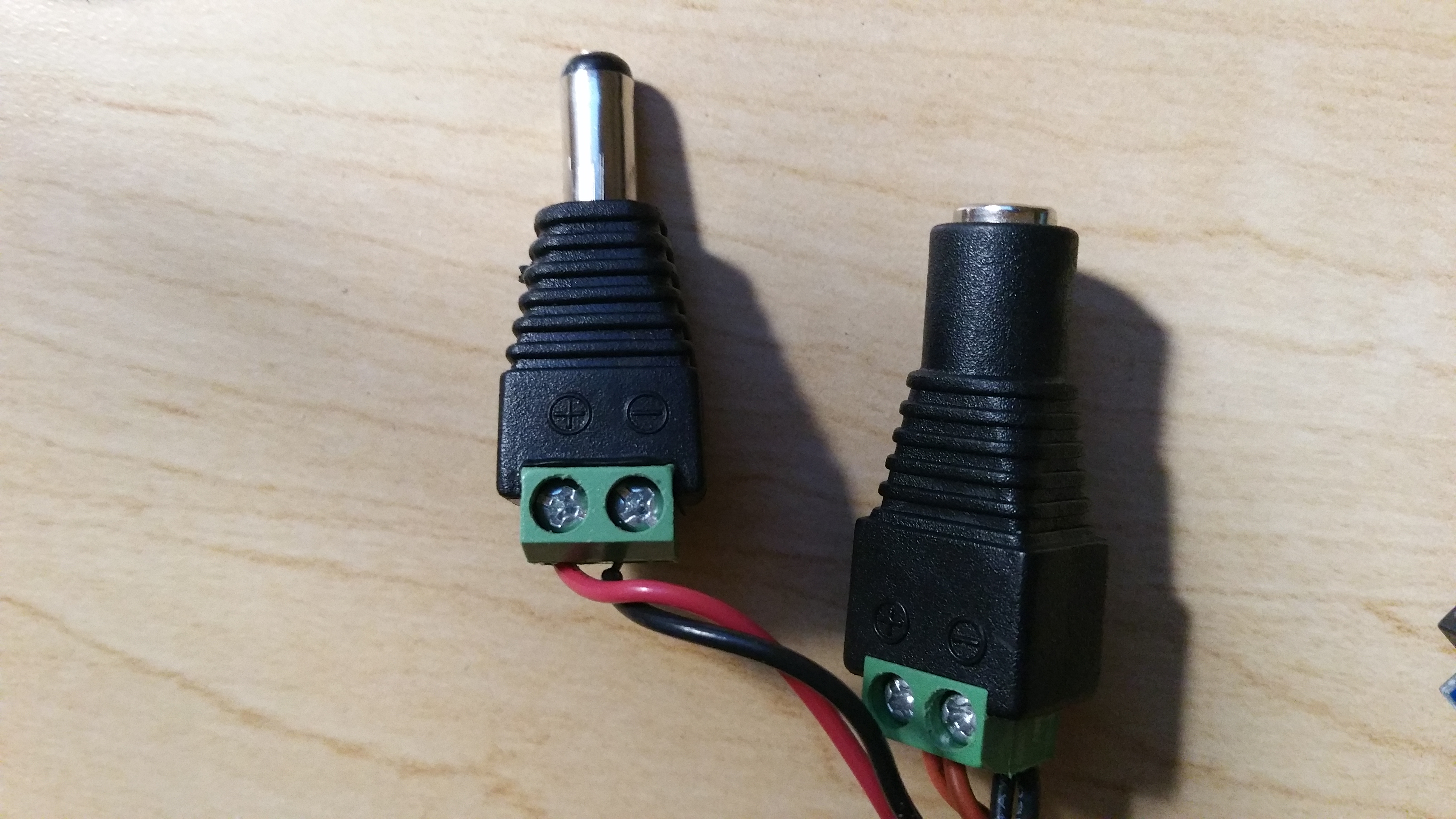
Step 2: Create a joint power supply cable
Using two pieces of red and black wires, a combined power cable can be created - of utmost importance is the use of a +/- DC jack, one with a male end, and the other with a female end.
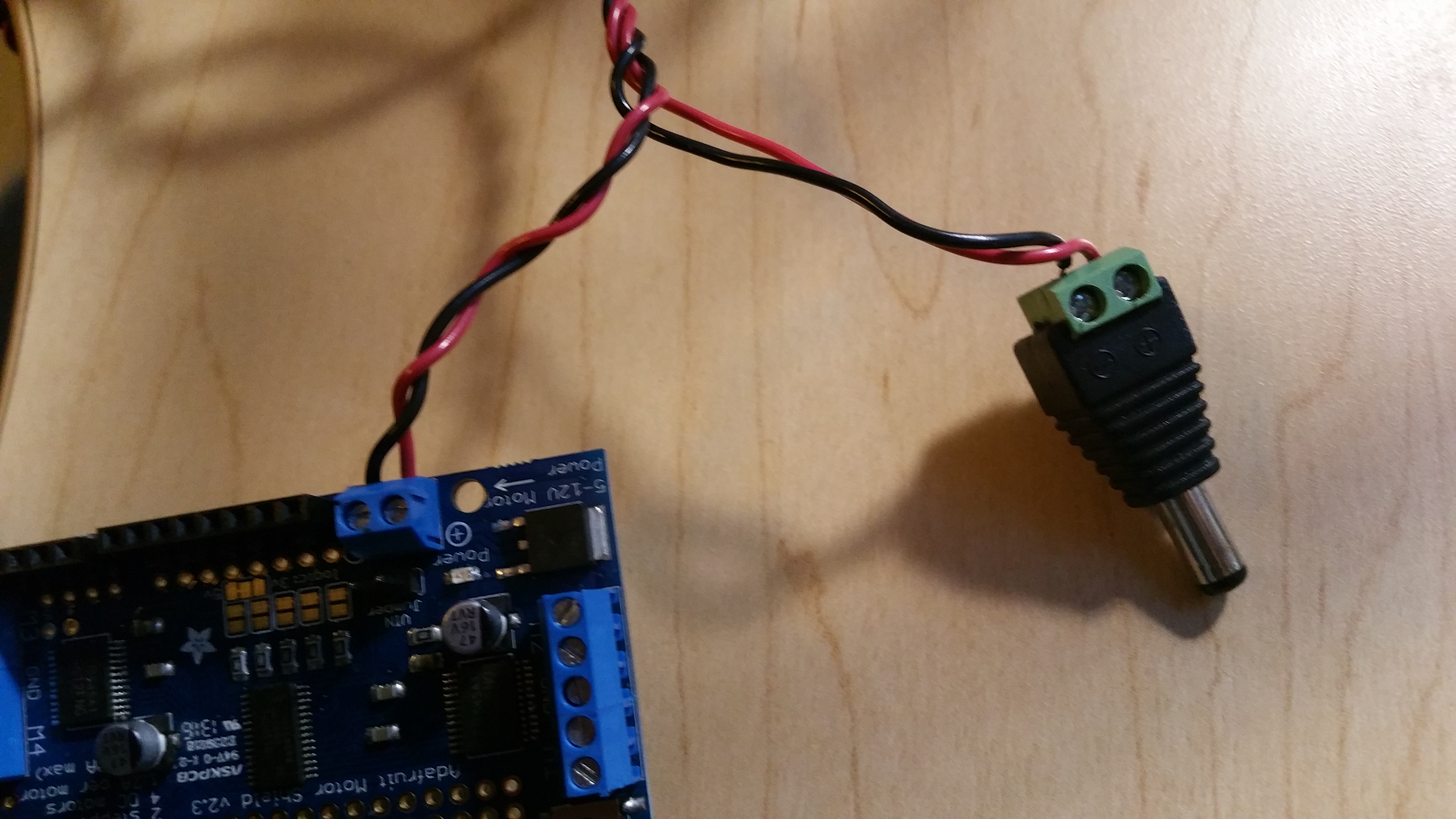
The male end will be used to connect to the motor shield’s 12V port, as shown below.
The female connector is directly interfaced to the DC power adaptor, which will supply power to both the motor shield and the Arduino board, if executed correctly.
Genderless molex connectors may be used to extend the wires if necessary - they should support a minimum of 4 wires, 2 for each output (to the Motor Shield and the Arduino respectively)
Step 3: Wire the motor ports
The Adafruit Motor Shield has four driving ports - these output jacks have a + and - polarity, and puts out 12V each. For this project, we will connect our motor wires to M3 and M1 respectively, due to the top and bottom orientation of the ports, which corresponds to the mechanical structure of the project.
Solder the other end of the wires to the motors’ ports respectively. Take care of the + and - signs when attempting to solder - an incorrect polarity may damage the motors.
Step 4: Install Arduino IDE (Internal Development Environment)
Get the latest copy of the Arduino IDE from:
This step is critical to the functionality of the code - as the Arduino uses a proprietary language (.ino), it requires a dedicated compiler that supports this language.
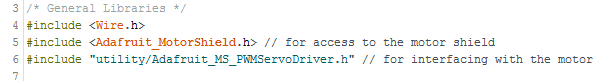
Step 5: Install additional libraries
The Arduino Motor Shield requires the use of header libraries associated with its proprietary functions - Adafruit_MotorShield() (AFMS).
To use them in Spectre, we need to install the added library Adafruit_MS_PWMServoDriver.h.
Upload the code from ArduinoClient.ino from a PC into the Uno. You will be required to use a USB cable for this procedure - avoid plugging in the DC jack while connected to the PC, as it may cause damage to the Arduino.
The libraries have been pre-included in the file, and will execute automatically, as long as the libraries are installed correctly, via the Tools section of the Arduino IDE (Add .zip library)
Raspberry Pi End
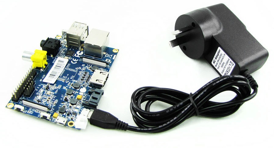
Step 1: Connect the Raspberry Pi to the micro USB power supply, HDMI and other peripherals
Using the 2.0A, 5V micro USB power supply, connect it to the DC input port of the Raspberry Pi.
Then, connect the HDMI cable to the monitor. (as shown below)
The Raspberry Pi supports HDMI natively, and does not require further setup to work.
Step 2: Connect microphone and speakers
For this project, a USB microphone is needed - most USB microphones come with its own sound card, which the Raspberry Pi requires to record sound physically (the Pi does not have its own sound card).
Attach the USB microphone to the Raspberry Pi’s Type A USB port (see Quick Peek for a visual guide)
Speakers are supported through a 3.5mm sound jack, and can be accessed with some minor OS tweaks (in software installation and configuration step)
Putting them together
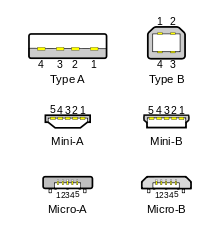
Step 1: Attach a USB Type B standard cable
There are 4 USB Type A ports on the Raspberry Pi, and a single USB Type B port on the Arduino.
To utilize the serial communication channel between the two boards, we will require the use of a USB Type A to Type B connector (see right)
By connecting them, both the Raspberry Pi and the Arduino side can become fully operational - enabling Spectre in its’ functional goals.
Install these electronics into the cabinet
Software Installations and Configurations
Install Raspbian
To get started, we recommend installing a fresh copy of Raspbian (Linux Desbian distribution specifically designed as a Raspberry Pi operating system) on your raspberry pi. You can find the download link and the installation instruction on the official Raspberry Pi website.
You will want to download the source code of Spectre project to get your own version of a smart mirror up and running. Please clone the Spectre source code repository by running following command from the Raspberry Pi terminal.
git clone https://github.com/SungwooPark/Spectre
Install Dependencies
Run the following commands from your Spectre git directory to install necessary dependencies to run Spectre software.
(You might have to run this command with sudo prefix.)
Create API keys
There’s a file called “APPID_Keys.py” on the top level of our github repository. It has a list of all the API keys assigned to empty placeholder values. For each of the key names in the list, you’ll have to create your own API key.
We’ll go through the list together. For each key you generate, assign the value to the variable name (i.e. newsAPPID = “12345”). You can do this by copy-and-pasting the generated key value straight into the APPID_Keys.py file.
newsAPPID -- click here (embed -- https://newsapi.org/account) to create an account and generate an API key for News API.
weatherAPPID -- click here (http://openweathermap.org/appid#use) to create an account and generate an API key for OpenWeatherMap.
Note: you will have to enable each Google API you use before you can use it. You can do this by going to https://console.developers.google.com/apis/library, selecting Google Maps Geocoding API, Google Maps Distance Matrix API, and Google Maps Time Zone API, one at a time, and clicking on the “ENABLE” button in the top right corner of the screen.
NewsBox-related API keys (NewsBox is not yet fully integrated on Raspberry Pi, so you may not need to get these API keys if you are using a Raspberry Pi)
indico_key -- click here (https://indico.io/dashboard/) to create an account and generate an API key for Indico.
consumer_key, consumer_secret, access_toke, access_token_key, access_token_secret -- click here https://apps.twitter.com/, log in to Twitter, and create a new app. Go to “Keys and Access Tokens” and copy and paste the values to their corresponding variable name.
Configure voice input and sound output
To enable use of external voice input and sound outputs, Raspbian OS must be tweaked -
Perform the following commands on the Raspberry Pi:
$ lsusb
Bus 001 Device 001: ID 0d8c:013c C-Media Electronics, Inc. CM108 Audio Controller
The above command ensures that the microphone is attached, and has an external audio card - after that, create a file known as asound.conf using the following commands:
$ sudo apt-get update $ sudo apt-get upgrade
(these commands ensure the OS and its dependencies are updated to the latest versions - USB sound depends on the ALSA library, which is a OS-level dependency)
$ sudo nano /etc/asound.conf
Insert these lines into the file:
pcm.!default { type hw card 1 } ctl.!default { type hw card 1 }
Pressing Control-X and Y will allow you to save these changes to file - these will allow the USB voice input to be the system’s default interface in applications, allowing the program to access it correctly.
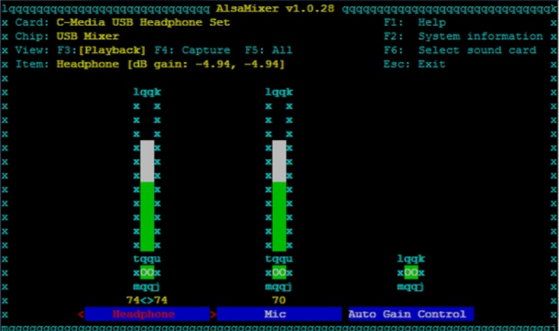
To check if the microphone and speakers are properly installed, you may run this command -
$ alsamixer -c 1
You should be able to identify the USB devices as uPnP USB Audio Device/Controller and set their input/output levels accordingly (see below).
Configure Google Cloud Speech API
On of the APIs that we are using is Google Cloud Speech API. To configure the Google API to work with Spectre, you have to install Cloud SDK, a command line interface for Google Cloud platform products. Follow instructions on the link below to configure Cloud SDK on your Raspberry Pi.
Extra setup is required to configure Google Cloud Speech API in addition to configuring Google SDK. Follow following steps to configure Google Cloud Speech API on your Raspberry Pi.
From command line, run following command from Spectre directory.
$python window.py
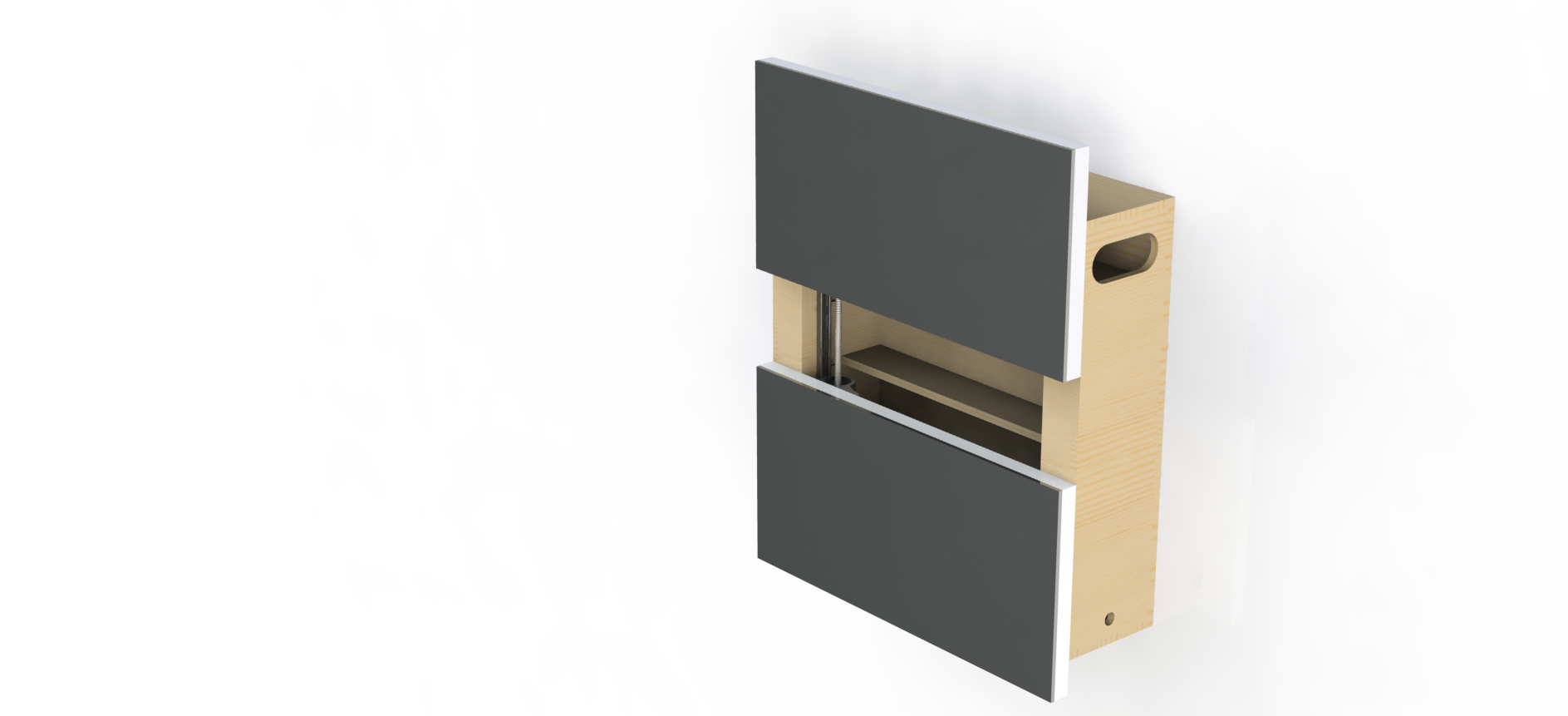
Mechanical Overview
Spectre is a smart mirror/smart cabinet system that includes a mechanically operated smart split-mirror system that opens to selected items in response to voice command.
For this project, the mechanical subteam designed and fabricated a wooden cabinet as well as two assemblies that could raise and lower mirrored screens. They also created compartments for each individual electrical component and ran wires throughout the structure.
The work was done over four sprints, which were individually blogged about as the project was completed. Feel free to peruse these at the top of this page!
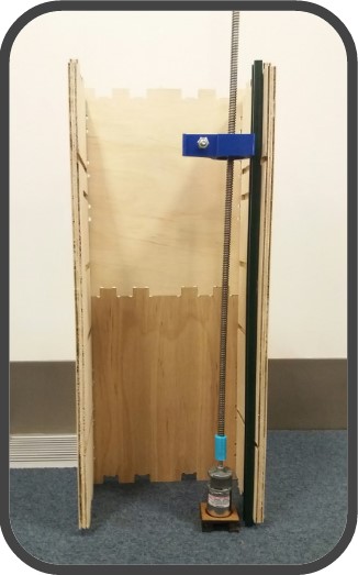
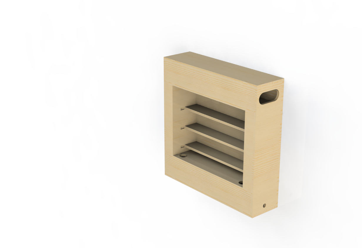
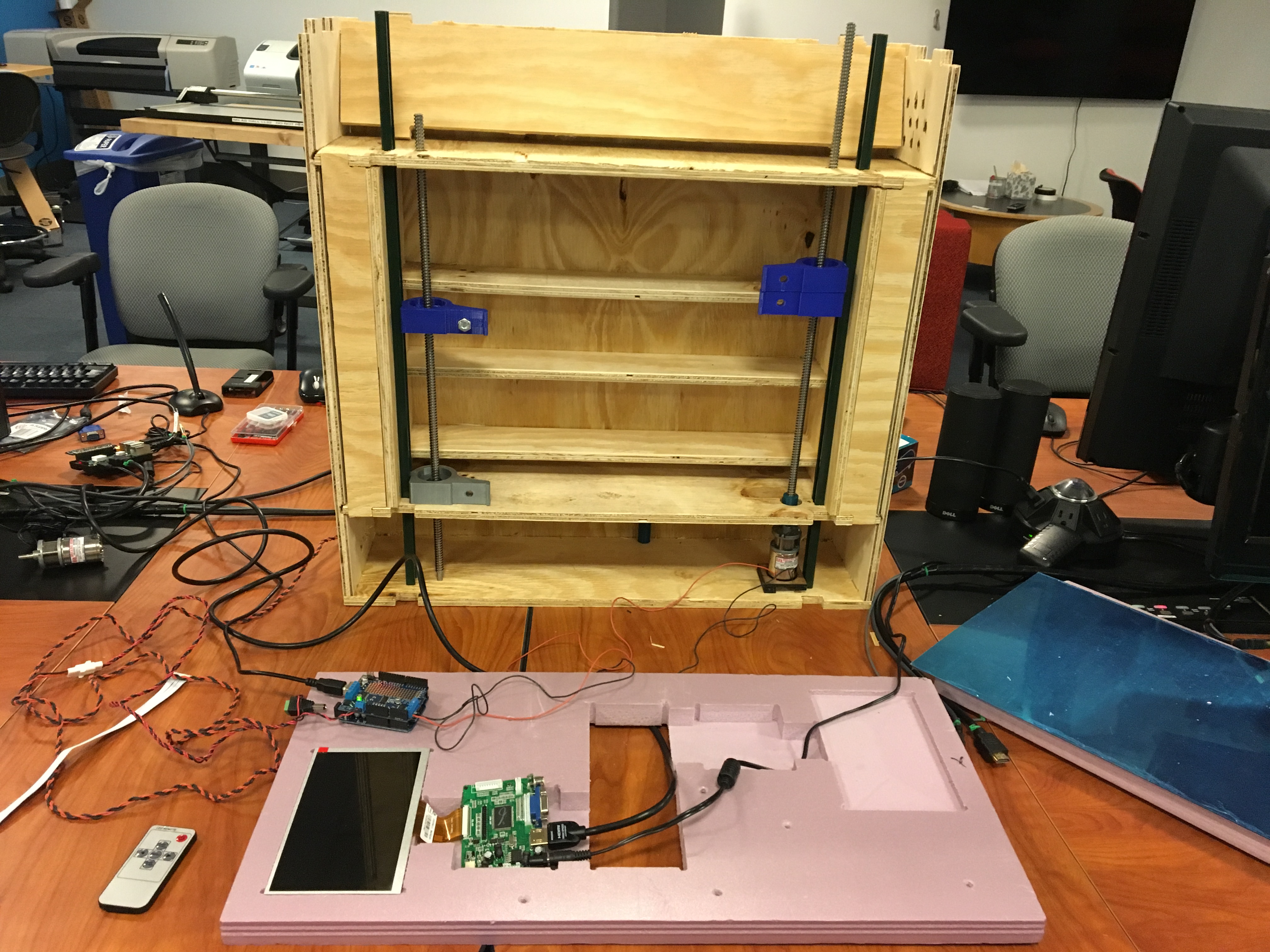
After several iterations, mistakes, and lessons learned, a 2 ft x 2 ft cabinet was shopbotted and constructed with two 1 ft x 2ft mirrors attached with screens behind them. Two lead screws were lathed and milled in order to connect them to the driving motors, and four 3D printed components were created to support the screens.
Two strut channels were cut to length and inserted into the cabinet in parallel with the lead screws. Foam supports were shopbotted in order to hold the screens and necessary electronic components tight against the mirror.
Sprint 1: Our Idea Generation and Proof of Concept
The main objective of this first sprint from a Mechanical perspective was to both come up with an overall project idea and to create a basic implementation of this idea in order to test our hypothesis that this would be a feasible project. After several conversations and some very detailed brainstorming sessions (see #Overview), we settled on the idea of working in a space which could involve human interaction with an everyday object. The idea that we came up with was a Smart Mirror and Smart Cabinet system, where a user could talk to the mirror and interact with the GUI, as well as use the cabinet for storage. Upon asking for certain items, the cabinet would open to pre-designated shelves in order to be efficient and useful.
Our vision for this product would be this smart mirror system that could provide information, entertainment, and convenience through the use of longitudinal motion, a split screen mechanical system, and a GUI. In order to reach that goal, we needed to complete our first phase integration with our proof-of-concept mechanical prototype, meaning that the mechanical subteam needed to hurry to complete a small scale working model.
Our first CAD model was very simple. The miniature cabinet was laser cut from hardboard, using tabs to lock the walls together. In order to move the screens up and down in opposite directions, we also laser cut a simple rack and pinion system that would be powered by small motors attached to the screens.
These motors and their respective gears would then cause the screens to climb up and down in opposite directions based on motor controller input. This seemed fairly simple when we completed the CAD, however when we went to build the system we realized a few serious errors. First, the rack and pinion system was not constrained in all directions, meaning that when we attached the screen to the front of the system, gravity caused it to fall right off. In order to counteract that in our rapid prototype, we hot glued on cardboard rails. This led us to the decision that in our next sprint we needed to change this longitudinal mechanism to something that is better constrained.
We also encountered trouble in trying to get the screens to lie parallel to the cabinet. We solved this in our proof-of-concept by wedging pieces of thick cardboard in between the screen and the cabinet to keep it vertical, but decided that in the next iteration we would need to think about how to keep everything parallel and vertical.
As you can see below, after plenty of work and way too much hot glue, we had a working prototype of our mechanical subsystem. We powered this by an Arduino and controlled the four motors with a motor controller. For this iteration, we just taped these components inside, but realized for later models we would need a specific place to put them.
We even made a brief demo video that could illustrate the longitudinal motion we were aiming for.
The next step was to integrate our software system. This required very little effort from the MechEs on the team, and we instead spent the time making sure that our fast prototype didn’t fall apart in the hands on the Software and Electrical subteams. After a lot of work and a VERY late night, we integrated the systems so that when the motors opened and closed the cabinet, our GUI could show it on the screen. The next step after this is to be able to tell the cabinet to open or close, then to have the GUI display what it heard on the screen while it is implanted in the physical system. You can see our demo below!
To sum up this sprint, here are two of our major realizations and solutions from this proof-of-concept model:
Realization:
Tolerance in the Rack-Pinion mechanism was too unstable, did not consider z direction constraint.
Underestimated gravity (weight of monitors)
Solution:
Use purchased gear, implement dovetail rails for support.
Decrease weight of screens by using LCD panels.
Our next sprint deliverable will include a full scale rack and pinion mechanism with a dovetail to lock it in the z-direction, and will have basic features such as time and weather in the UI written from scratch.
The main order of business for the Mechanical subteam this sprint was to take the first key steps towards our finished mechanical design. This included redesigning our linear actuation method as well as redesigning our cabinet to fit all of the full-sized components. We aimed to CAD and Shopbot this new cabinet as well as build and demonstrate a new assembly replacing the previous rack and pinion assembly). This all needed to be integrated with the electrical system in order to run the motors, and the software system in order to have voice recognition control the motors.
The CAD for the cabinet this sprint was fairly easy, however when we actually went to shopbot the sides, the slots designed for the shelves to fit into were not cut deep enough. This meant that actually assembling all of the shelves as well as the top and bottom of the cabinet would have used a lot of our remaining time and effort. Instead, we chose to focus our efforts on just getting a new lead screw assembly working consistently.
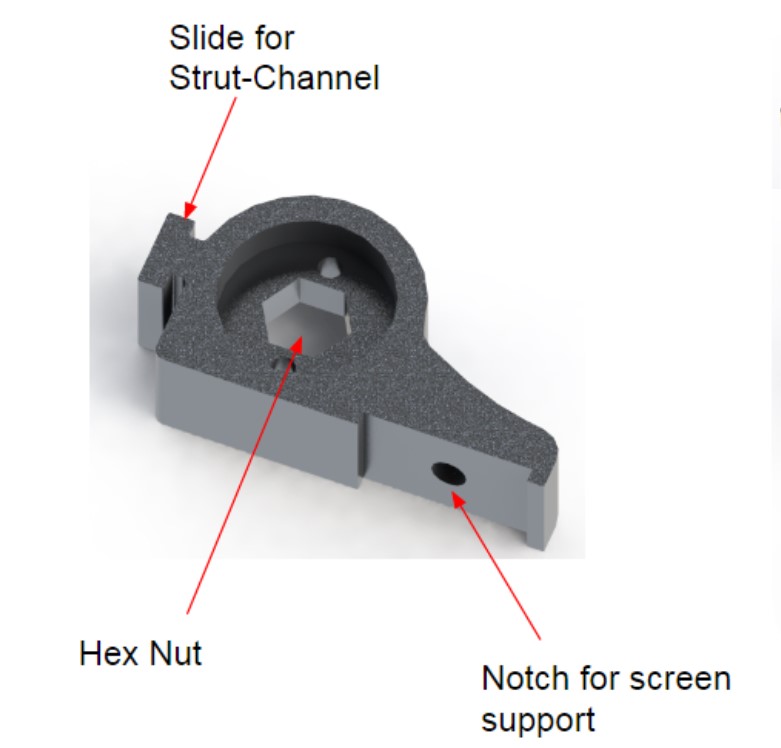
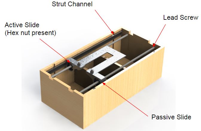
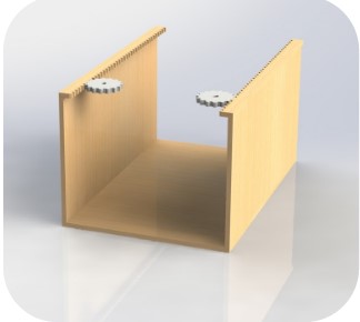
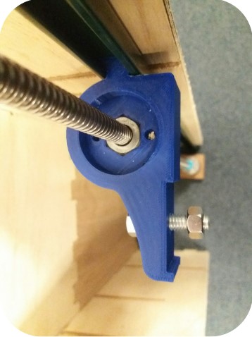
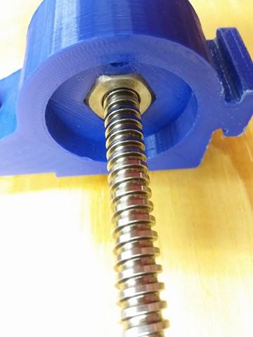
The lead screw assembly we designed to replace the rack and pinion assembly was a better choice because it locked all of the pieces into a parallel line. Each side consisted of two 3D printed pieces (one with a hex nut and one without), a lead screw, a motor, and a strut channel.
The 3D printed piece with the hex nut was used as the active slide, driving the attached screen up and down the lead screw. The strut channel and the passive slide on the other side ensured that the screens never rotated and ensured that the assembly had as little friction as possible. You can see our overall assembly below.
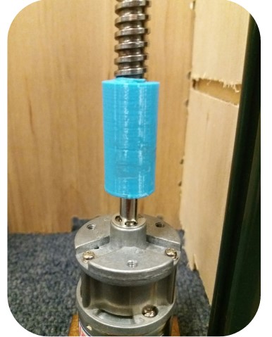
For this sprint, we were only able to get one of these assemblies working due to issues connecting the lead screw to the motor. We ended up 3D printing a coupling, however it was not a clean solution for long term use due to it’s lack of concentricity.
We decided that for our next sprint we would like to find a better rotational attachment method, and we looked into buying different couplings. One proposed method that we may pursue next sprint is to turn down the lead screw into a d-shaft to ensure that they continue to rotate together without slipping.
Sprint 3 started off with Thanksgiving, which meant all the machining and manufacturing team had no choice but to go on vacation! As a result, Monday after Thanksgiving, the mechanical and electrical team had a 5 hour hackathon. The main tasks we had for Sprint 3 were:
Re-CADing/ShopBotting the cabinet due to major wire housing issues
CADing/ShopBotting the foam screen frame
Turning/Milling the lead screw into a D-shaft
3D printing the lead screw-motor shaft connectors
CADing/3D printing the motor brackets
Yeah. It was a lot. It was time to face the reality and really get to work.
CAD,CAD,CAD,BAD,SAD… ☹
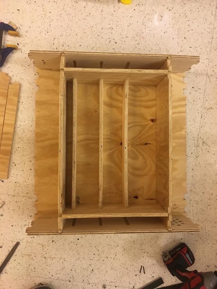
Tips to consider when dealing with voice recognition: you need speakers and microphones, I mean good speakers and good microphones. So, under as poor as our team was, we managed to get decently functioning hardware, just not decently sized ones. Due to poor communication with the other sub-teams and hasty decisions, we had to re-CAD our cabinet to have bigger shelves on the top and the bottom to fit all the hardware and wiring we had. Also, we added side shelves on either side of the cabinet for the wires from the motor shield to the motors would run down with less strain.
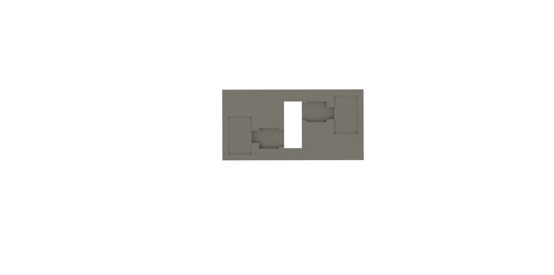
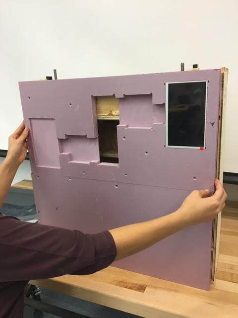
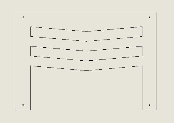
After abandoning our idea of wooden frames for the screens and the mirrors due to weight contrainsts, we pivotted to using a much lighter material: foam. Getting the inspiration from the Macbook – etching the main frame and making housing for each components to fit nicely – we CAD-ed something that looks like this.
The shallow pockets are for the screens to be flush to the mirror as possible (for best resolution of screens), the deep pockets for the breadboard to fit tightly, and the slot in the middle for the power source and the HDMI cables to pass through.
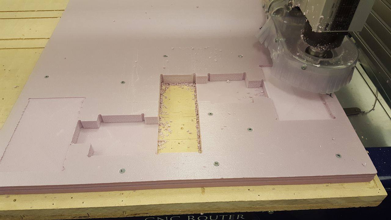
Ready,Set,Shopbot!
In an ideal world and situation, Shopbotting really shouldn’t take that long. All you do is export each of the parts as DXF, load them to V-carve (software for the Shopbot), secure your piece to the cut board, and cut away! However, budgets are real and so are machine failures.
The most difficult part of Shopbotting the cabinet was laying out the cut parts on the plywood that was available to us. Due to budget limitations (again), we had to fit 14 different pieces, most of which were 24 inches in length, on two 2 by 4 and one 2 by 2 pieces of plywood. The difficulty of this comes from securing the stock in order to properly cut the pieces. As you can see in the picture of the Shopbot cutting the foam, the screws have to be close, yet far enough from the bit in order to prevent the piece from moving and keep the bit from running into the screws. So next time, remember: THINK STOCK BEFORE DESIGNING.
After a total of 11 hours with the Shopbot, we were done! Haha. No we were not.
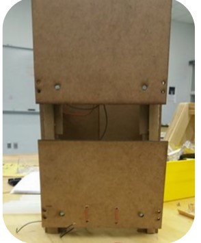
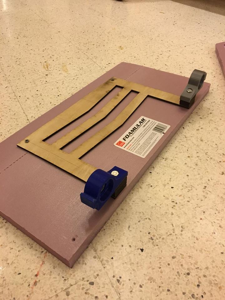
The foam frame worked out great. We got the perfect tolerance for the screens to press-fit into the foam and stay secure and flush to the surface.
Nevertheless, we had another 3 to go on sanding/assembling the entire thing. As I mentioned before, machine failures happen. We set the pocket dept to the width of the stock, but the Shopbot did not carve it as deep as it was told, and the shelves couldn’t slide in. So… Oh boy, did we file the sh* out of that thing. And, finally, we had our assembly of the cabinet!!!
Trust me, I’m a (mechanical) Engineer.
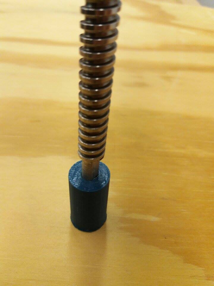
I’ll be honest, making D-shafts are not that hard if you know how to work on the lathe and the mill. You just turn your stock down to the desired diameter, then mill however much you want to create the D shape. So we thought.
Both of us have barely worked on the machines since we got trained, which was almost a year ago, and didn’t do the best job of being consistent with our spec sheet. We had two wonky looking D-shafts that had to be concentrically coupled to the D-shaft of the motors. Now having experience with the tolerance on the Makerbots, we decided to print the shaft connectors 10 thou (0.01 inch) smaller than the actual D-shaft and hand-file them to a snuggle fit.
INSERT PIC OF SHAFT, CONNECTOR HERE
Success…? I guess…?
Like all sprints, we had our ups and downs with this one. CADing and getting the Shopbot components done were a success, but the 3D printed parts (motor brackets and shaft connectors) ended up being non-usuable because the tolerances were off.
Success!
Failure.
With just one more sprint to go, will Spectre be able to pull this off till the demo day? Stay tuned for the result in the Sprint 4 blog post!
"Behind every meaningful object, living or otherwise, is an electrical pulse"
The electronics behind Spectre is an ever growing journey - one that is largely characterized by its iconic bluepritns, and that of its growth.
Forging an assembly of electronic components to create an autonomous, voice-activated mirror cabinet system, the electrical system has evolved rapidly through the course of 4 sprints - each with procedural goals.
In Sprint 1, we worked to establish a proof-of-concept - with an explicit goal of achieving mechanization and a form of synchronized display.
This was largely successful, opening the pathways to multiple possibilities for the next Sprint -
One such pathway was in speech recognition - it was a natural choice, given the use cases that the product was envisioned for (in the bathroom, or in highly constrained areas).
This resulted in the development of external voice I/O capabilities to support the drive for voice activation.
Another pathway was in the form of a more stable, efficient use of motors in our design. Through cross-domain efforts, we were able to to reduce the amount of motors to two, from four initial PWM (pulse width modulation) servo motors.
Finally, everything comes together in a serial architecture between the Raspberry Pi and the Arduino - a handshaking process allows the Arduino to actuate based on voice commands issued to the Pi, then providing suitable feedback to the Pi when the process is ongoing or done. This allows the mechanization to function with the accuracy required of its’ design.
Click on each Sprint’s blog post to learn more about the (many) technical decisions that we had to make on the electrical frontier, and how we overcame and learnt from them.
“When we first began, we only knew one thing - that it was going to be smart; It was going to be a mirror that everyone would dream of having in their bathroom.”
Humble Beginnings
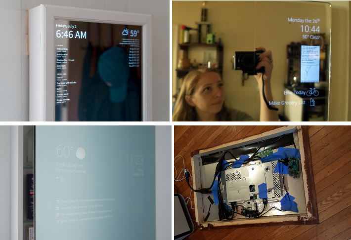
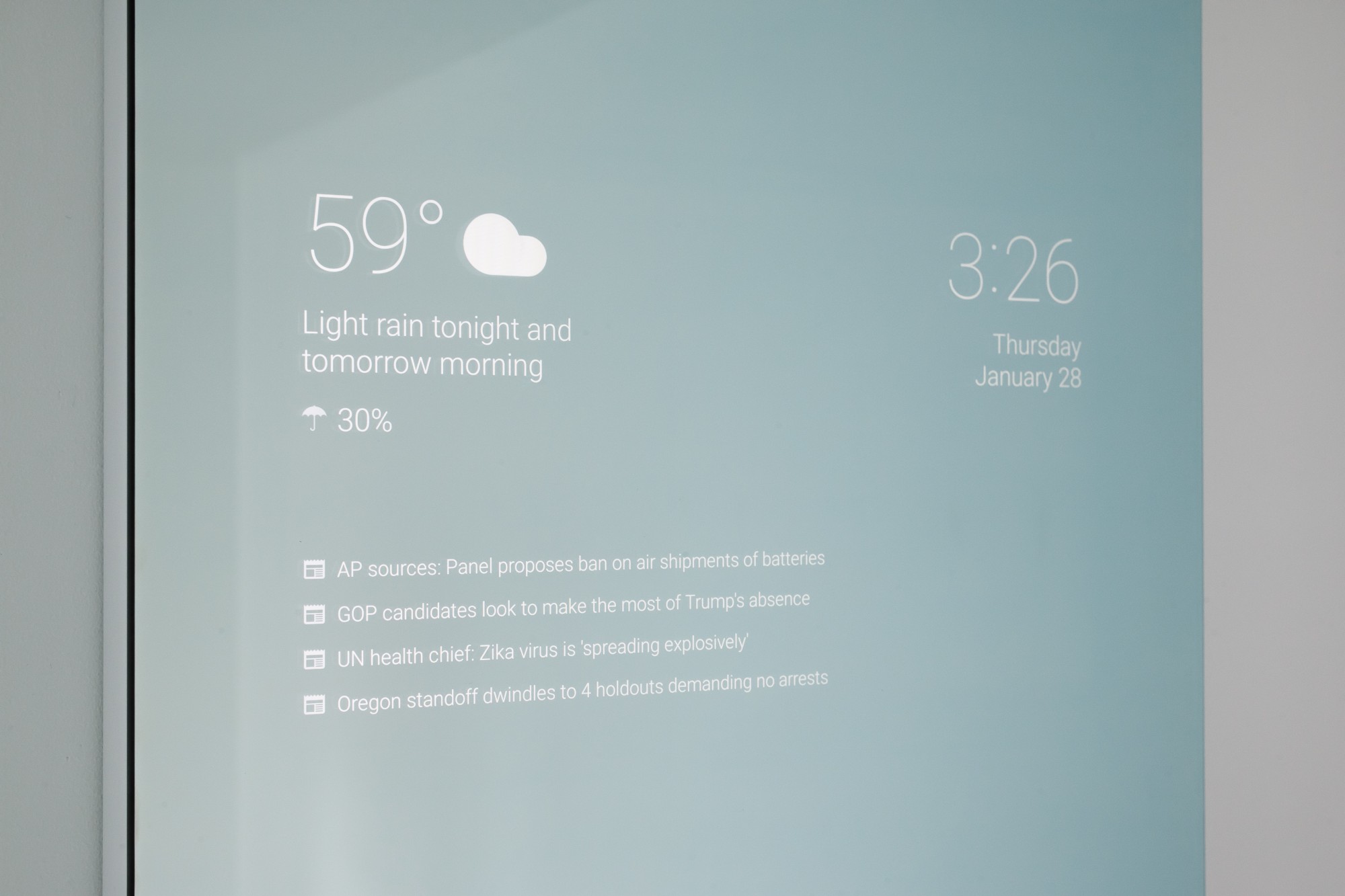
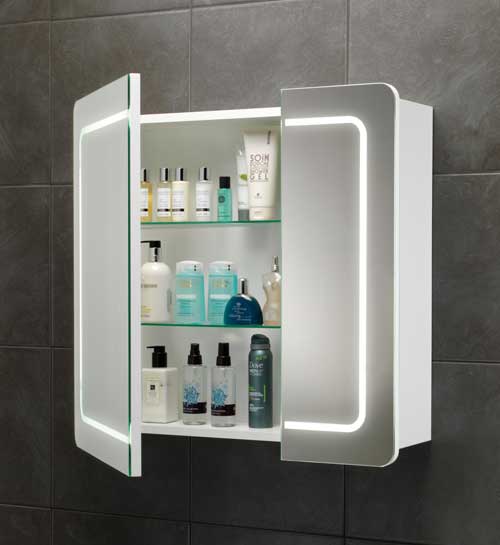
We drew our vision from a couple of known DIY projects on Youtube and social media - each of them visionary in their own way.
Exhibit A: A couple of DIY projects that inspired our project’s vision
These projects were refined to various levels - each of them had a different approach to creation, whether it was the electronics used, the mechanical assembly, or the OS (Operating System) and codebase.
For us, we wanted to build something differentiated - a first of its kind - with mechanization and a split body system. We wanted more than just a mirror - it had to also double as a cabinet.
Enter the Prototype
So we set about to build what would be our proof-of-concept, and a first prototype: a key goal was to achieve a stable form of mechanization, and provide a simple form of interactive feedback to the user.
Electrical Architecture
Every masterpiece needs a sound architecture - so we set about to lay the foundations that would facilitate and provision for the final design.
Exhibit B: The first iteration of our electrical layout
Critical to this sprint was deciding what was needed electronically to provide the front-facing UI (User Interface), and the mechanizing backend (operating the motors).
We considered the possibility of employing an all-in-one (AIO) solution, but bumped into several considerations that made us reconsider :
The lack of I/Os (interfacing is terribly important)
Computation limitations of using a single device
Burnout (of course, overheating!)
So we went with a two-device architecture - the Raspberry Pi would serve as the front-facing UI, with network and stronger computational abilities to support graphical demands of such a task, while the Arduino Uno would drive the motors through its motor shield, which was capable of handling a wider range of voltages and power requirements.
Arduino and the Motors
Developments on the Arduino front was critical to our first-stage proof-of-concept - electrically, we wanted to see how many motors were actually required to support our project’s vision, and how it was going to possible to drive it with a single Arduino.
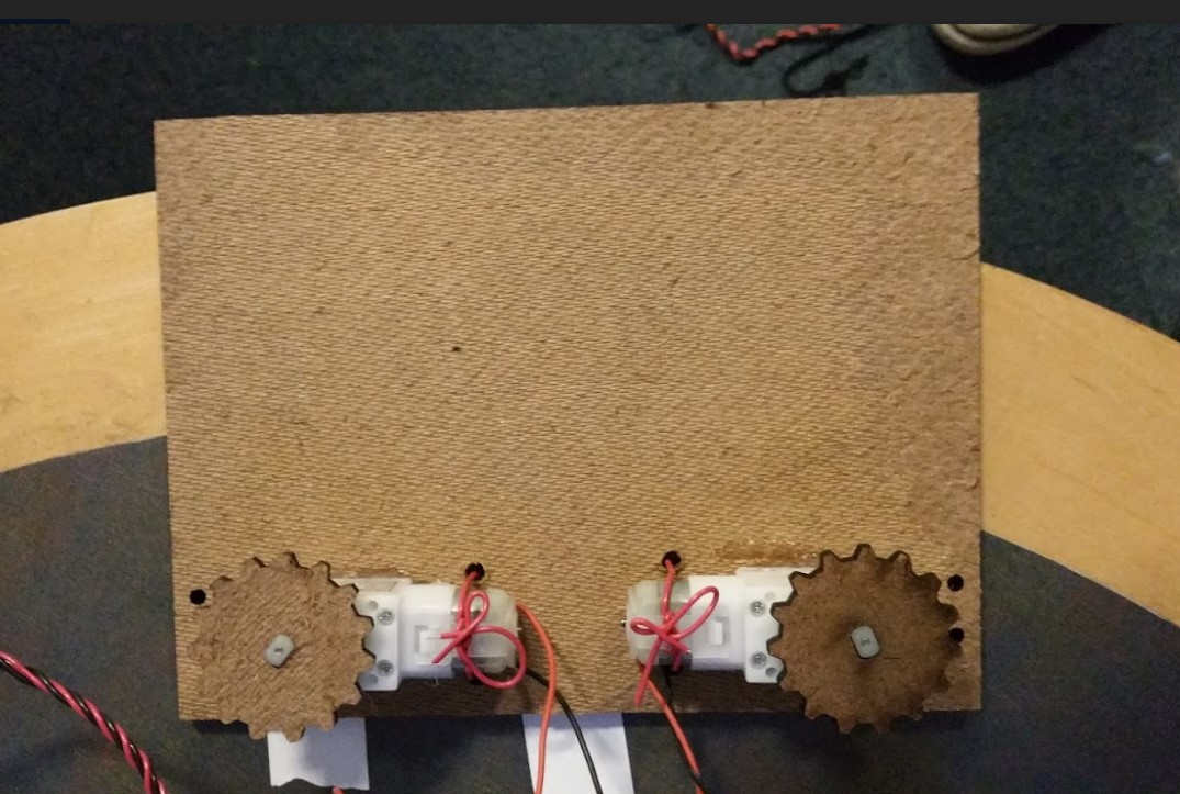
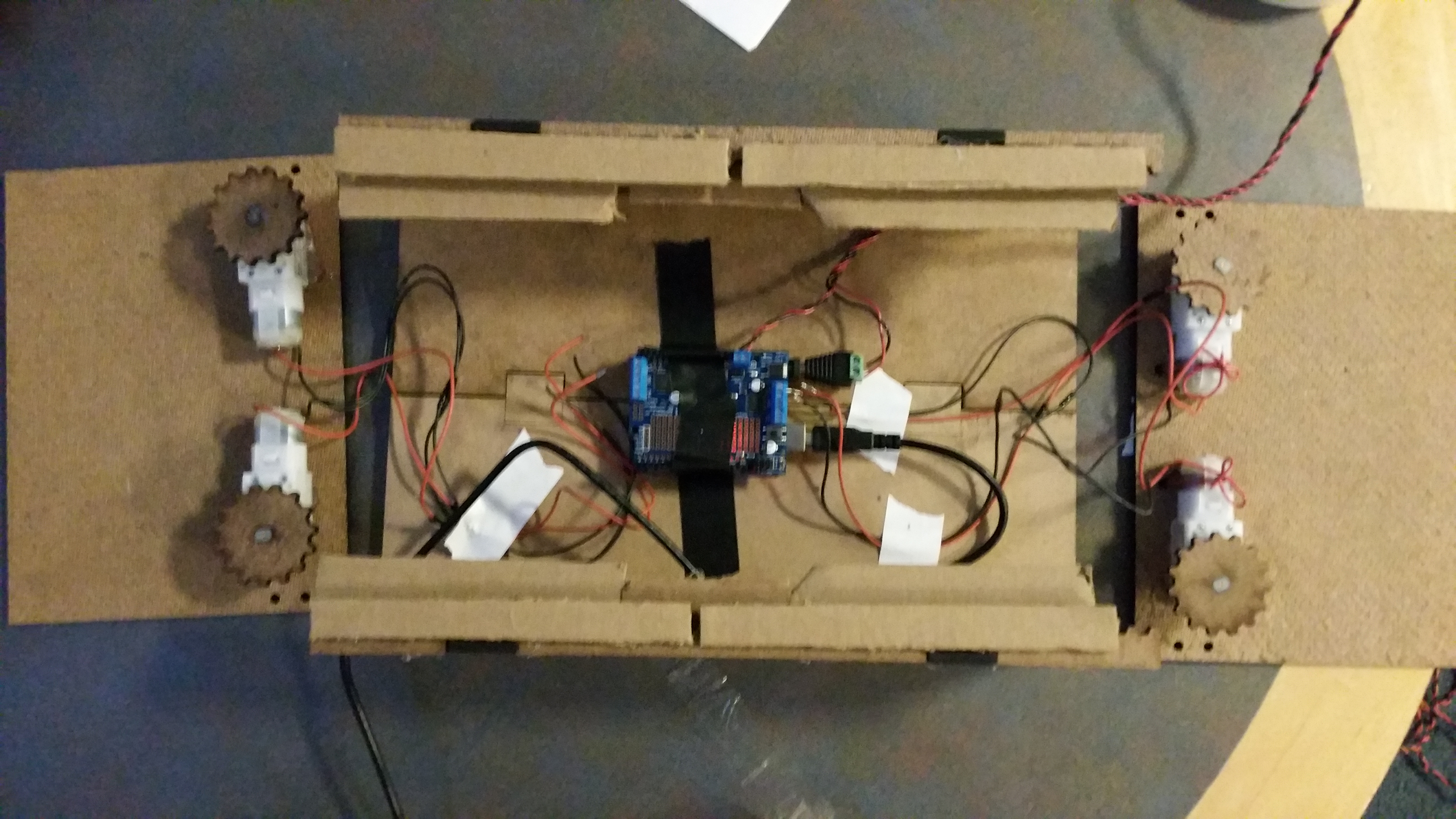
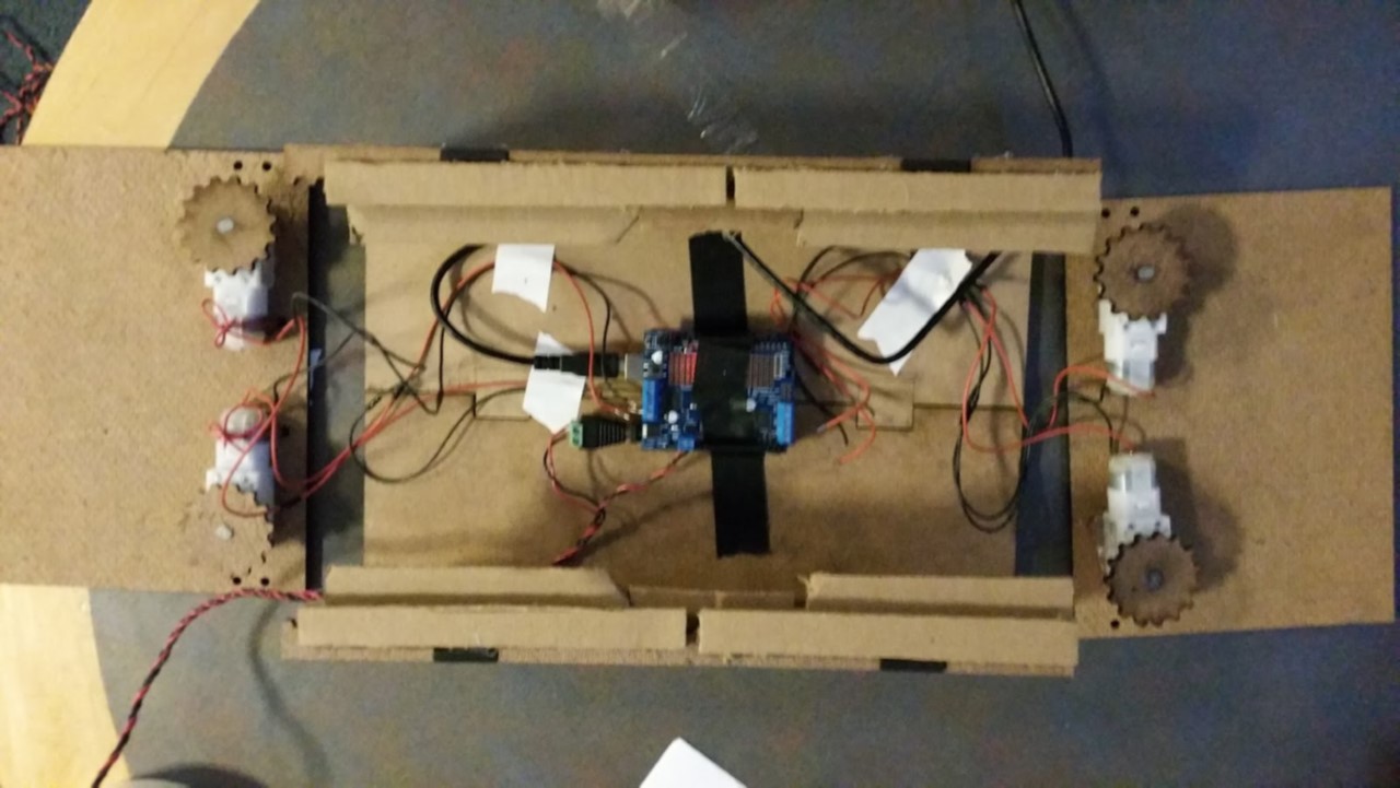
We made a quick and dirty wiring layout - with functionality in mind:
Exhibit C: Inside the belly of the cardboard beast
The prototype turned out to be largely successful - we were able to mechanize the our mirror - and key developments came from the code and I/Os.
I/O
Here are the parts used for this Sprint:
Vigor Precision BO-7 PWM Motors (DC 12v)
Arduino Uno R3 (will be used permanently)
A ton of wires
Adafruit Motor Shield V2
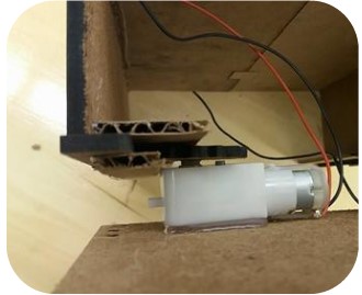
After loads of hard work putting the wires and controllers into place - voila, a complete prototype 1!
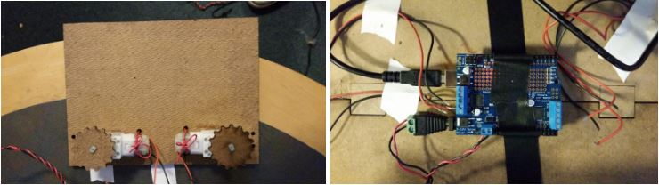
Exhibit D: The motors and the Arduino’s (messy) wiring
“A lot of cool interaction ideas. Which are you prioritizing?”
“ Music is a must, maybe having a light that you can tell the mirror to turn on. ”
“ How are you going to make sure that both motors on one screen move
simultaneously (at the same speed) and stay aligned with each other? ”
“ It looks pretty good. I'd reconsider the two screen system though ”
“How will this change once you add an actual mirror? Do you need an actual mirror? ”
Expansion & Redevelopment
One of the biggest takeaways from the last sprint was a need to redesign the way our motors carried the load - a rack and pinion system was unable to sustain movement continuously, and the torque would put a big question on its longevity.
On top of that, interactivity was also a big question - what kind of inputs were we to take? Our attempts at tinkering with emotional control were limited at best, and we needed an intuitive way to interact with the mirror.
Voice: the new frontier
Enter voice - this was a decision crafted out of necessity: for one, nobody was going to have their fingerprints all over a mirror. A keyboard and mouse would be out of the place too. From there, it was simple - we had to expand our electronic master plan to provision for voice input and output.
By the second sprint, we were starting to face the beginnings of a port constraint - the Raspberry Pi had only 4 USB ports, and they were already allocated as such:
WiFi Support
Arduino Serial Communication
Keyboard and Mouse
Empty
The HDMI port was taken up for the display, and besides the lone USB port, only the 3.5 mm audio jack remained available.
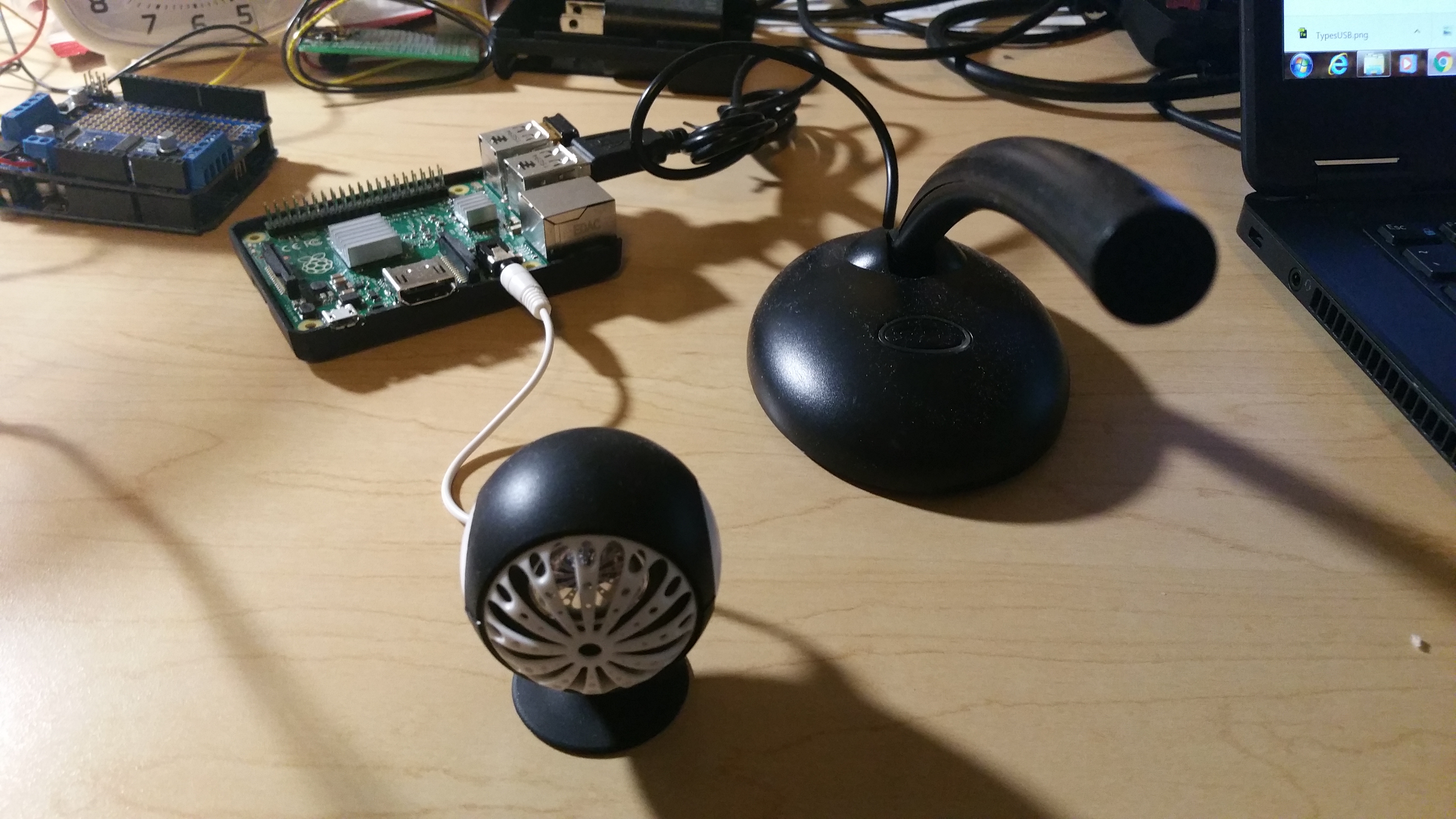
We had to seize our chances - the speakers were an easy choice for the 3.5mm - but was the microphone usable through the USB?
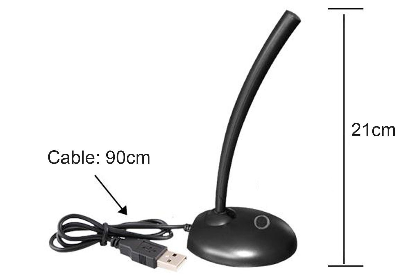
Budget was also a real thing - we had to rebuild the chassis for the mechanical housing, and so frugality was a goal, aside from functionality. We bought this nice little microphone from Amazon, hoping it will do the trick.
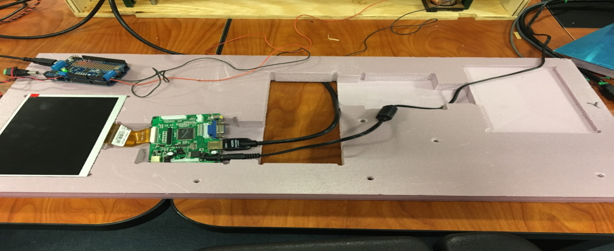
Exhibit A: Doing a test fit on the 3.5mm jack and USB
It turns out it was actually a good decision - the external sound card on the USB microphone was exactly what we needed for the Pi to be able to take voice input.
Calibrating it however, was hours of development hell - the Pi wasn’t able to recognize or use the microphone immediately, but we were able to remedy that after applying a suite of diagnosis commands. (i.e. lsusb, dmesg, etc.)
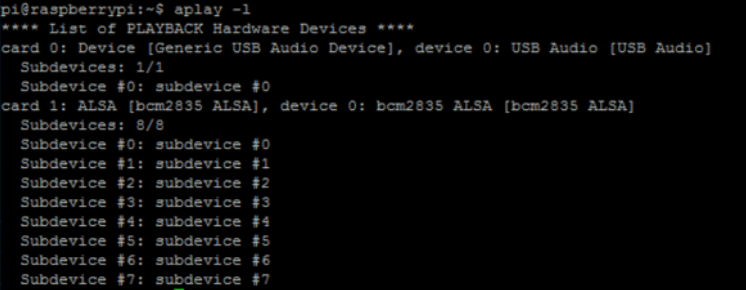
(Protip: use aplay -l, arecord -l to find playback and recording devices on any Raspbian OS)
Exhibit B: Finding our “generic” USB audio device
The card and bus information was really important to successfully getting Python to recognize the correct voice device for input, and it was a well effort spent.
4 out, 2 in : the motor revolution
On the mechanical front, we learnt that the rack and pinion system was not going to work as well as we had hoped it to.
This realization prompted a radical redesign of the entire case (which is covered in the mechanical subteam sprint review), and with it, a need to relook at the motors we were using.
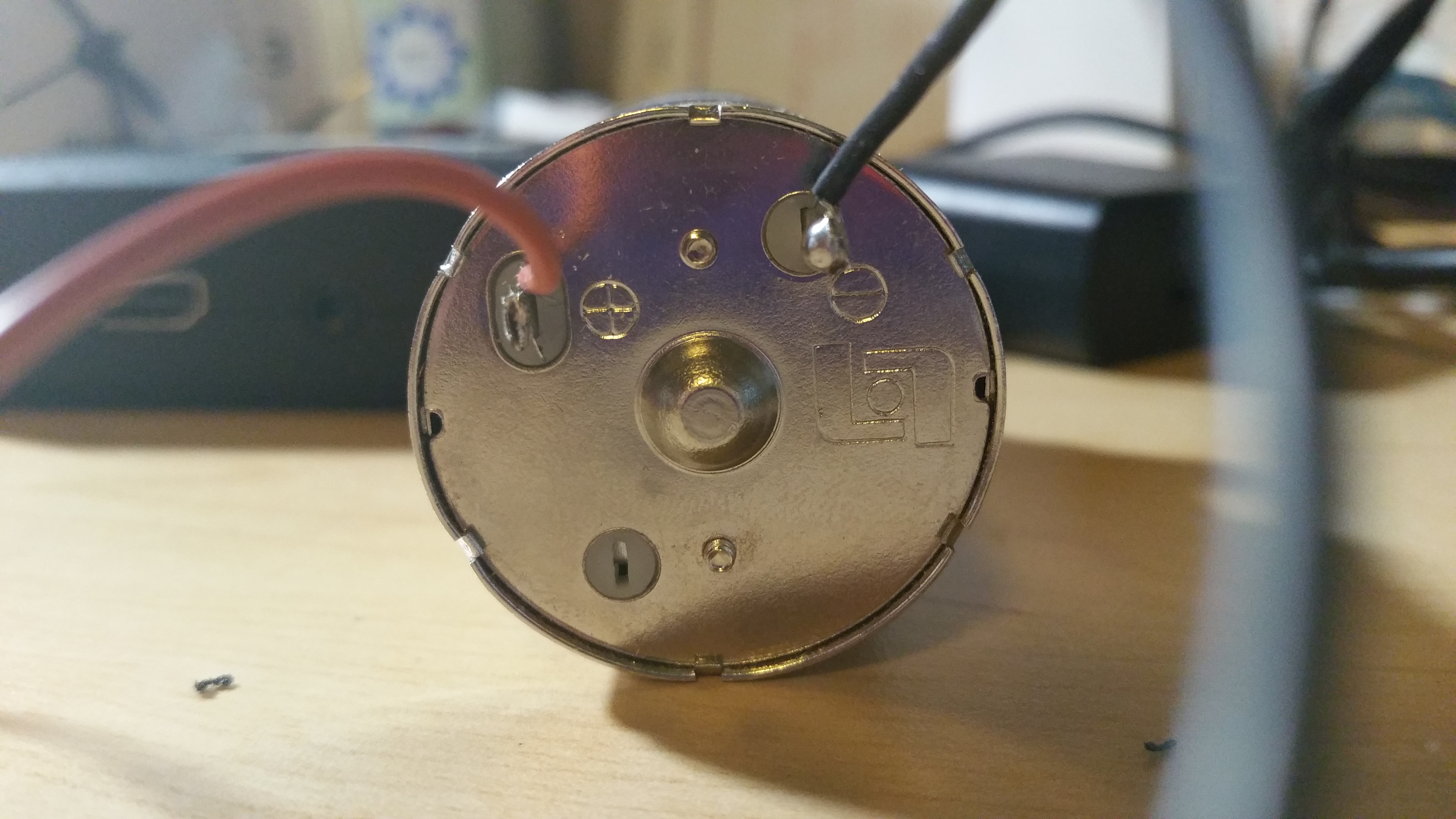
Before this, we were using these motors from Vigor Precision, which were highly similar to the ones used in our PoE labs:
Exhibit C: PWM Motors from Vigor Precision
However, we soon realized that it wasn’t enough - we needed something that could produce more torque, and was efficient enough to reduce the net amount of motors required to mechanize the structure.
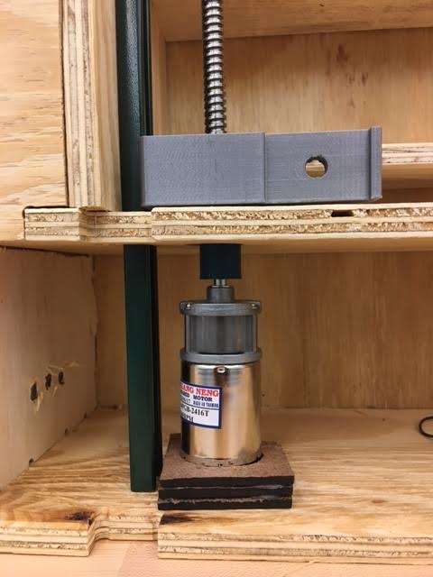
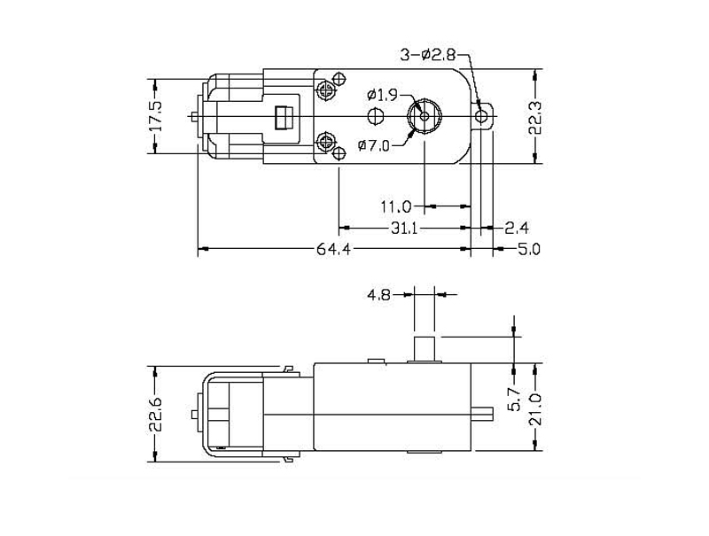
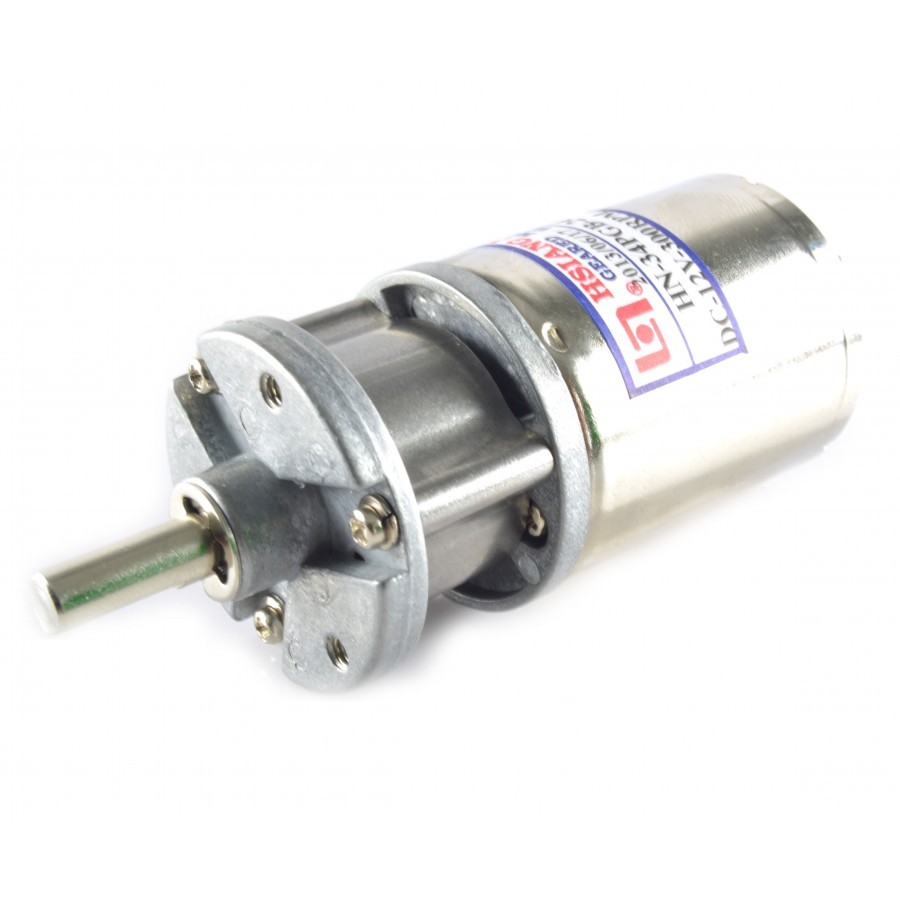
After some discussions, we decided to utilize two planetary gear motors instead - these were 12V motors, each capable of putting out about 3.5 times the amount of torque than the previous motors.
Alas! Almost ¾ into development and we’ve never looked more primed to deliver a promising final product.
At the end of the last sprint, a few things happened - each of the subteams achieved some form of breakthrough in terms of functionality, but had limited opportunity to truly integrate their work.
In other words, we didn't have it all together. Yet.
This sprint was going to solve that - a big come-together, merry-go-round, bridge between the mechanical frame and the cool GUI we laid out.
At the centre of that bridge, would be wires and electrical signals, chips and boards.
Big Time, Screen Time
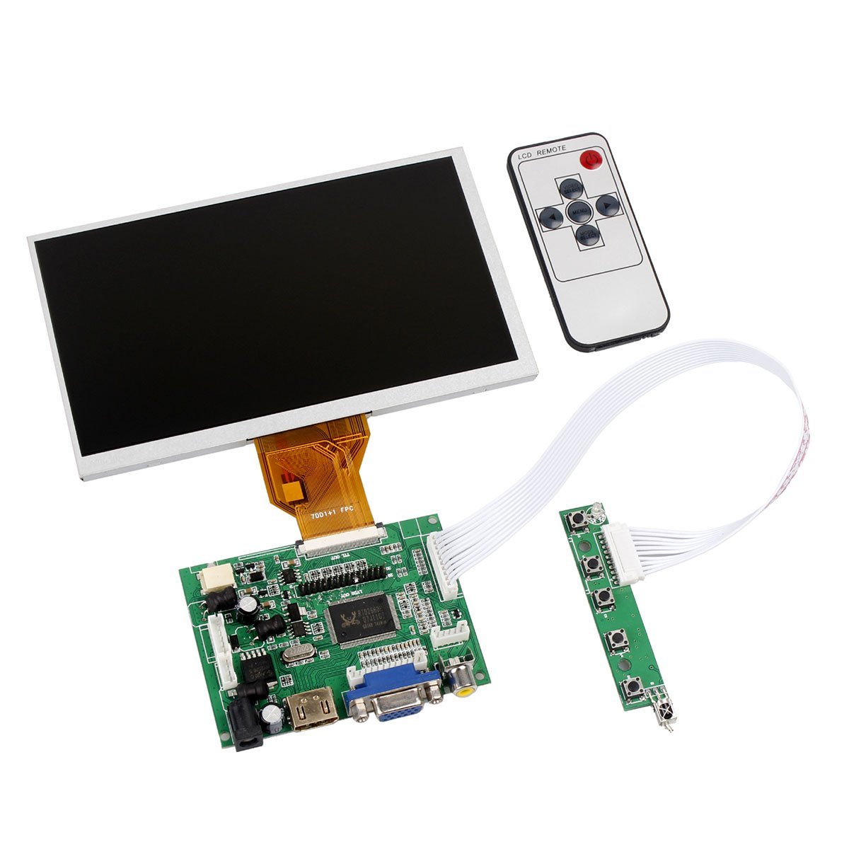
To kick off the final process, we added two screens from Amazon to our inventory - they seemed a little flimsy, but they were the most affordable 7” screens we could get our hands on at the time.
The best part about these screens was the controller board (which incidentally, also contributed to the failure of the second screen) - it was able to support both HDMI and VGA-based input.
However, they required separate power sources, which created a significant bulk in terms of housing, but it was great to know that the mechanical team was able to work around it.
During the same period, the mechanical design was also updated to reflect a new, vertical screen orientation - this required us to rethink the UI and the OS’s natural orientation. We had to position a fix for this:
sudo <text editor name> /boot/config.txt
And we added this: display_rotate=1
This made the OS boot naturally in a vertical mode (90 degrees CCW), which was successfully extended to the UI, when we launched the Python code on it.
One Last Port
With almost every other port exhausted on the Raspberry Pi (at the end of the last Sprint), we were getting desperate - how do we get a secondary display out of this $35 mini-computer?
Fortunately, after doing some research, we discovered that there was a way to “coax” a VGA output using the GPIO pins available on the Raspberry Pi.
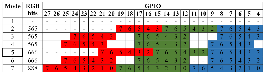
Courtesy of Gert Van Loo, his resistance bridge design allows the GPIO pins to simulate up to 900K colors (about 262K per color band in RGB)
We utilized the 666 mode - which was equivalent to 6 bits/channel on the red, green and blue bands respectively. This required a grand total of 21 GPIO pins, leaving only 6 pins left to use (GPIO pins 22 - 27). Talk about efficiency!
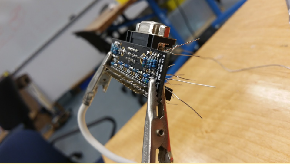
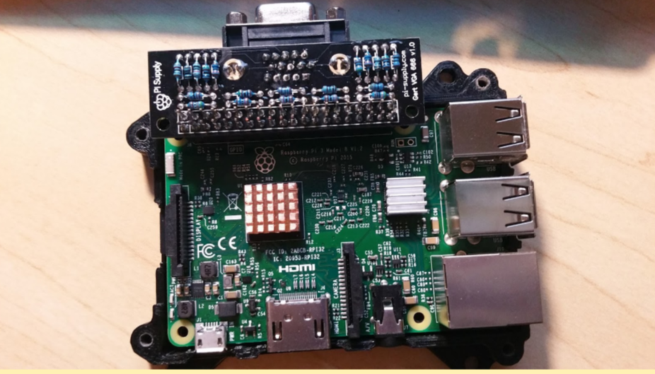
After a good amount of soldering and short-testing, we have the final product:
However, when it was finally put to the test, we soon realized it was too good to be true -
The Raspberry Pi’s GPU was easily overexerted by the graphical intensity of two screens
The VGA screen wasn’t actually a real screen - it was just a limited extension, relegated to playing videos, projecting photos, and other non-desktop functionality.
This was the first true electrical setback - and to add to that, was the unfortunate meltdown of one of the two LCD display boards - our tight budgetary constraints led to a cheap buy off Amazon, and the screen interface board (see below) suffered electrostatic damage during assembly.
So in the end, we settled for a one-sided solution - maybe just for now - (I would really like to fix this):
The user interacts with Spectre by talking to it. Since Spectre is intended to be a bathroom mirror and cabinet, it doesn’t make sense for there to be a physical interface -- that is, the user probably shouldn’t be clicking a mouse or touching the mirror mid-handwash when they suddenly want to know the weather in Houston. So, we use voice-recognition to control what Spectre does and shows.
Spectre displays information (more on this in the Features section) that the user requests using Tkinter, Python's standard GUI package. As of this writing, Spectre only has one LCD screen on which to display the Tkinter window, but we hope to add a second screen, as it will allow Spectre to show the user more information at any given time.
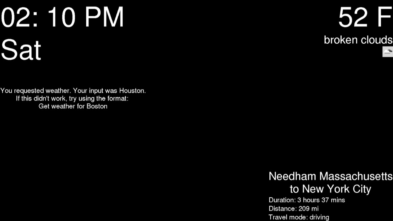
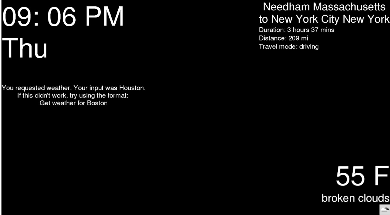
We use Google Cloud’s Speech API to handle voice recognition, and we incorporated a feedback widget in the program to help the user understand the format in which different features should be requested (i.e. our program understands “get weather for Houston” but not “how’s Houston’s weather right now?”). The feedback widget picks up the keyword in a command (i.e. weather) and tells the user the format for that command. Spectre works together with the user to make sure it understands what the user wants.
Features
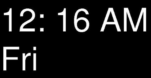
Spectre encapsulates its features in widgets (full list of widgets below). This makes it easy to modularize our code. The user has almost full control over what widgets they see and when they see them, with the exception of the clock widget, which is always visible in the top left corner of the screen.
Widgets can be pinned to the bottom right corner of the screen if the user wants them visible permanently (or, until they unpin them). We recommend the user pin only one or two widgets to keep the window from becoming too cluttered, but they can pin as many as they want. When the user requests a widget, it is temporarily placed in the “focus” position, located along the top right corner of the screen. Only one widget ever occupies this spot, and when a new widget is requested, the new widget replaces the old widget, or takes “focus” (if the widget being replaced was a pinned widget, it resumes its spot at the bottom right corner of the window).
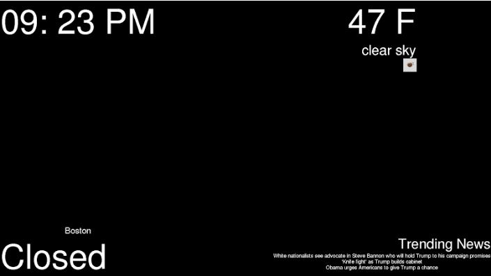
The screenshot below shows the weather widget in “focus” and the trip widget pinned. You can also see the clock widget at the top left corner of the screen and the feedback widget below it. The most recent command was “get weather for Houston.”
Widgets
Clock: time and day of the week
Change timezone
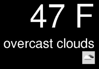
Weather: temperature in Fahrenheit, short description of sky (i.e. “slightly overcast”), and weather icon (i.e. picture of cloud)
Change location
News: top three headlines from news source
Change news source (70 choices)
Trip: distance and duration for trip from one location to another
Change origin and destination
Change method of transportation (car, walking, bicycling, or public transit)
Mirror: mirror status (opening or closing)
Change mirror’s position (open or closed)
*NewsBox: choropleth map of US showing polarity of tweets with given search term
Change search term
Feedback: voice recognition assistance
*Not implemented on Raspberry Pi as of this writing (problem installing dependency)
For a typical, stationary smart mirror, you need three things: a mirror, Raspberry Pi, and LCD screen. While our smart mirror also has a mechanical component (moving up and down), the non-embedded part of our software works similarly to many of the smart mirrors you’ll see on the internet. We have a GUI (Graphical User Interface) that displays information, and we have a method of interacting with that GUI that doesn’t require a physical interface (because you don’t want to be touching your mirror mid-handwash when you suddenly need to know the weather in London).
The first thing we did was look for a toolkit with which we could build our own custom GUI. Our main constraint was language -- we decided to use Python because it was a language Sung and I (the software subteam) both knew and favored. We came across the Tkinter module on HacketHouseYT’s Smart-Mirror Github repository (link below) when we were perusing the code of other smart mirror projects for inspiration (unfortunately, smart mirror projects done in Python are relatively rare). Tkinter is a standard Python GUI package that acts as Python wrapper around a complete Tcl interpreter embedded in the Python interpreter. If that sounded like gibberish to you, don’t worry -- it sounds like gibberish to me too.
My first sprint largely comprised of Tkinter experimentation. I used tkinterbook as my primary guide (link below). There are three main Tkinter concepts you need to understand: widgets, frames, and the window. We’ll start with the latter. The window is the whole screen generated by running your Python program with Tkinter. Everything you put in your Tkinter GUI will be in the window, and everything will have a position relative to the window (TOP, RIGHT, LEFT, or BOTTOM). The window is the Tk object. You place Frames inside the window; a Tkinter Frame is basically a rectangle that holds widgets -- which we’ll get to shortly. When you create a Frame, you specify what side of the window you want it to touch and it creates a rectangle resting against that side.
Finally, there are widgets. Widgets are small, stand-alone objects that generally have one purpose (i.e. clock, weather information). You place widgets inside Frames, and you specify what side of the Frame you want that widget to touch (like you do with Frames in the window), but more specifically (i.e. NE of TOP or S of LEFT). Tkinter has a number of built-in widgets you can use (technically, Frame itself is a widget).
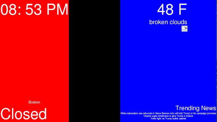
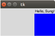
Whew. That was a lot of text. Here’s a visual to assuage your impending headache. The picture below shows you the GUI we have now (end of Sprint 2) with the Frames highlighted. We’re currently using two Frames: left (red) and right (blue). Within the Frames we have a number of small widgets -- more on that later. As you can see, the Frames are rectangles that are placed relative to the window; one Frame is on the LEFT side and the other is on the RIGHT side. The window is the entire picture, if that wasn’t clear! The black rectangle is space in the window where there is no Frame.
And here’s our current GUI without highlighted Frames. It’s marginally nicer to look at.
So how did we get here (second picture)?
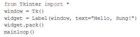
I started by creating a simple Label widget that had some text on it -- I didn’t even bother to put it in a Frame at first. Again, the tkinterbook proved to be a helpful resource here. The code to accomplish this was five lines; you can see it below (credit to tkinterbook).
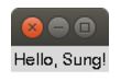
You create the window and the widget. Then, you pack the widget, which means you place it in the window, and run a loop, which produces the image below.
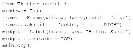
This was straightforward, and I quickly moved on to incorporating the next big thing: Frames. I started by creating one Frame on the RIGHT side of the window and placing the Label widget in it (code shown below).
The first parameter we pass the Frame widget is where it’s going -- the window, in this case. We also pass the background color so we can easily distinguish between the Frame and the window, but this is one of many optional parameters. Then, we pack the Frame into the window like we previously did with the Label widget. Again, we pass in some optional parameters; “fill” determines whether or not the Frame fills the x and y directions. If the Frame is against the LEFT or RIGHT side and fill is set to “both” or “y”, it will completely fill the y direction but only the width of its widgets in the x direction, and if it’s against the TOP or BOTTOM side and fill is set to “both” or “x”, it will do the opposite with regards to the height of its widgets.
The “side” parameter of frame determines what side of window the Frame touches. Similarly, the “side” parameter of widget determines what side of frame the widget touches. Just like we packed the widget into the window in our previous example, we must pack the Frame into the window and the widget into the Frame in order to accomplish our goal of placing the Label widget within the Frame. The fruit of what are likely confusing efforts are below.
At this point, we integrated our program with the electrical and mechanical subteams’ work, which was very easy. They had rigged up a structure that could open and close, so we connected the arduino they were using to our Pi via a serial connection, read from the Arduino whether or not the structure was opening and closing, and continuously updated the text in our Label widget to reflect whether or not the mechanical system was opening or closing. The video we took of this is here. It’s a very rudimentary system, but it was a solid proof of concept that we could have a moving mirror that interfaced with a GUI on a RaspberryPi.
So, we figured out what GUI toolkit we’re going to use and the basics of how to create a GUI with it -- what next?
I’m glad you asked! And no, I’m only a little crazy. Next, we started adding basic widgets to our GUI. Our smart mirror is meant to hang above a bathroom sink, so users would primarily see it in the morning while they’re getting ready for work or school and at night, when they’re going to bed. With that in mind, some relevant information for the user would be time, weather, news, calendar alerts, traffic to a destination, or an inspirational quote for someone who really just wants to go back to bed. In our second sprint, we were able to implement three of these pieces of information in the form of three widgets: clock, weather, and trending news headlines.
NOTE: For the sake of space, we won’t be including any of the code for our widgets here; you can find them in the window.py script in our repository.
We started with the clock widget. Python has clocks built in, so the code was very simple. We created a clock class with a Label widget to show the time, instantiated it, and placed the instance into a Frame in our GUI, like we did before with the Label widget that said “Hello, Sung!” It produces the image below (albeit with the current time) in the top left corner of the window.
The next widget we implemented was our weather widget. Retrieving the weather required an API, and we decided to use the OpenWeatherMap API to get the weather data for a given city as well as the Requests API to make the HTTP request to OpenWeatherMap’s API. Links to both APIs are included below. The weather data is returned via the Requests API as JSON, so we had to parse the data to get the information we wanted: the temperature (which we converted from Kelvin to Fahrenheit -- seriously, who uses Kelvin?), the description (i.e. “Clear” or “Rain”), and the weather icon ID (which we then used to retrieve the picture of the weather icon via another HTTP request). We displayed this information in three Label widgets, as you can see in the snapshot below.
The third and final widget we implemented in Sprint 2 was a trending news headlines widget. We used the Requests API with another API, creatively called “News API”, to fetch metadata for articles from a chosen news source (CNN) with an optional “sortBy” parameter (top news, latest news, or popular news -- we chose top news). The article metadata included the headlines, and since the mirror has limited space, we decided to only include the headlines of the top three articles in our GUI. We show this in another Label widget with a second Label widget as the title, Trending News.
Of course, the time, weather, and trending news changes over time, so we implemented an update method that gets called every time our main loop runs. The update method calls update methods in each class (clock, weather, and news) to update their labels with new information. It doesn’t make sense to recheck the weather and trending news every second or so, so we created a counter that only updates the weather and news every five minutes. The time is continuously updated.
Well, that’s great and all, but what if I live in Cheyenne, Wyoming and I don’t want the weather information I’m getting to be for Boston (which is the hardcoded default)? Firstly, we at Spectre formally recommend you move. Secondly, thank you for bringing up our next talking point!
We’re using voice recognition software as our interface between the user and our program. You can find more information about the specifics of our voice recognition program below in “Speech Recognition Program”; we’ll focus on integration here.
Our voice recognition program is very resource-intensive (time-wise), so running it on the same thread as the update method slows the updates down, which isn’t detrimental since they don’t currently need to be particularly frequent, but is clunky and could at some point present a problem. So, we decided to move our voice recognition program to its own thread, so the main update method and voice recognition program could run in parallel. The downside of doing this, however, was that it made it harder to relay the results of the voice recognition program (“get me weather for Cheyenne”) to the main program, because they were on separate threads. This meant it was difficult to update the information (change city in weather class to Cheyenne) in response to a vocal command, because they two processes happened independently.
We decided to use a queue to solve this problem. We pass it into the speech recognition program when we instantiate it in our main window, which allows our main program to read commands added to the queue by the speech recognition program from its separate thread. It was a surprisingly simple fix!
We’re still trying to figure out the specifics of how we’ll respond to voice commands -- for now, we’ve integrated changing the city we get weather for, but the voice command has to follow a very specific format for that to work so it’s not an ideal end solution (the script searches for keyword “weather”; if keyword “weather” is in the command, the program assumes the last word in the command is the city and changes the weather class’s city to that string -- example command: “get weather for Cheyenne”. Fingers crossed you don’t live in a city with a two word name).
At the very least, our current program provides both a GUI and a non-physical user interface. Oh, and we have a rudimentary chatbot integrated. Almost forgot about that little guy. He’s pretty dumb, but he can respond to questions...sometimes.
Speech Recognition
We want to give users a variety of experiences and information while using our smart mirror system. Many components of the User Interface (“UI”) require an interaction between the mirror-system and the user, but our design of the smart mirror does not include a physical component for user input, like a keyboard or buttons. Our solution was to add voice recognition capability to the software system.
Instead of building a speech recognition and speech-to-text engine from a scratch, we decided to use a library that we can simply plug into our application.
“Good artists copy, great artists steal.” - Pablo Picasso
Just like how great software engineers do themselves a favor by being as lazy as possible to get the job done, we decided to focus our precious time and energy to something that we are interested in (and truly passionate about), which was to deliver meaningful and useful experience to the user of our smart mirror system.
It’s written in and for Python (the Masterminds behind Spectre don’t know refuse to work in any other language than Python. Also, my boss told me to add here that she knows Java too).
It’s looked simplest among the speech recognition libraries that showed up when we googled ‘Python speech recognition’.
It is actually pretty simple to use.
It supports multiple speech recognition engines.
Installing and using this library is quite straightforward*. I will not waste time of whoever’s reading this by skipping detailed instructions of how to install and implement the library. If you are interested in that, check our documentation that will be available eventually.
*If everything goes well. We were able to easily install everything on a laptop that we are testing our mirror UI. However, when we tried to install everything on Raspberry Pi, we had to cry for a bit. We will include what exactly happened during our installation process on Raspberry Pi in our documentation (that we promise to make eventually).
However, there are few interesting things that are worth noting. We had to install another dependency called PyAudio because we were using a microphone to get a user’s speech. Also, we had to set up Google Speech Recognition API by doing things like signing up for Google Cloud Engine and getting API keys.
So we said installing and using the speech recognition library is pretty simple. Well, what we really meant was that the installation will be simple for you (future users) because we went through a trouble of encountering all sorts of bugs that you might experience instead of you. Check our beautiful documentation (again, not here yet but will be soon) for more details.
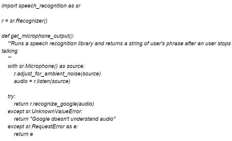
Installation might have been little troublesome, but once everything got set up, using speech recognition was actually really simple.
Initialize speech recognition instance
Adjust microphone for an ambient noise
Get microphone input
Run a method that calls Google speech recognition API
That wasn’t bad at all.
We have JARVIS now.
Hmm, well. No.
Our current speech recognition interface has quite few problems.
First of all, the latency for our speech recognition call is abysmal. It takes ~20-30 seconds for a single sentence to be recognized. Fixing this problem will be our main priority.
Secondly, the current interface between the speech recognition script and the rest of the mirror UI is not quite what we want. The downside of using a simple speech recognition library was that what it does is also quite simple. Currently, our speech recognition script listens to anything a user says and execute a specific instruction if it hears a specific keyword. Because our program isn’t really understanding a sentence as a whole, the interaction through current voice recognition set up is pretty limited.
For example, our program displays a weather of certain city when it hears a word “weather.” The system assumes that a user will say something like, “How’s the weather in Boston?” so it takes the last word of a sentence as a city name and displays the weather information for that city. However, what if someone says, “How is Boston’s weather?” What if we want to do something more with weather information? Like giving weather forecast instead of only current weather.
Obviously, there are a lot of things that we have to work on. But we are still proud of what we have so far. Interested in what our system is currently capable of doing? Check out a video below; it’s a demo video of our current work on the software end of things (end of Sprint 2).
The software subteam started Sprint 3 with a close approximation of our MVP. We had a GUI with a few basic widgets, a method of controlling the GUI that, while infuriatingly slow, worked well enough, and an interface between the UI and serial connection to tell the Arduino when to open or close the mirror. All of which is to say, we had the brain of a smart mirror, but it was the brain of the dumbest smart mirror around.
So, we spent Sprint 3 trying to make our smart mirror smarter. First, we restructured our code: Clean house, clean mind. At the start of Sprint 3, our main program, window.py, included all of our widget classes and was over 200 lines long (as of the beginning of Sprint 4, it is ironically the same length, but it would have been much longer if we didn’t clean it up!) . We knew we wanted to add more functionality to the existing widgets as well as add new widgets, so we decided to break up the script and put each widget’s class in its own file. This did not affect fullWindow (GUI object) at all -- we instantiate the widgets in the same way we did before, in the same place. The only difference is now we’re importing the widget classes instead of calling them from within the main file.
As we added more widgets over the course of this sprint, our repository became cluttered, so we also implemented a folder system to organize our repo. We have two folders: Speech and Widgets. The Speech folder contains all of the files related to our voice recognition and chatbot programs, and the Widgets folder contains all of the scripts and other files pertaining to our widgets. Only the main program (window.py), API keys script, and requirements files remain on the top level of our repository (as of this writing!). Modularizing our code like this makes it easier to find and edit scripts.
Moving on to more fun things: We added two new widgets! Our trip widget takes in an origin and destination and calculates the distance and duration of the trip. The NewsBox widget, our second new addition to the widgets family, was Sung and I’s final project for Software Design. It takes in a search term and displays a choropleth map of the average polarity of tweets with that term in different regions of the US -- we’ll explain this more later! In addition to adding two new widgets to our program, we also gave the clock and news widgets an upgrade. The clock widget can now display the local time for a given location and the news widget can give you the news from one of 70 sources.
We’ll start with the trip widget. We use Google Maps Distance Matrix API to find the distance and duration of a trip from one location to another. Google’s location-related APIs tend to be very flexible about the format in which locations are given (i.e. it will take Needham as well as Needham, MA, or 1000 Olin Way or lat/lon coordinates). If the given address is not unique (i.e. there are four Toledo’s in the US), Google’s location API’s will use region-biasing to guess which address you meant, which means they’ll factor in the location of your request (probably wherever you are). Someone searching for Toledo in Ohio is probably looking for Toledo, Ohio.
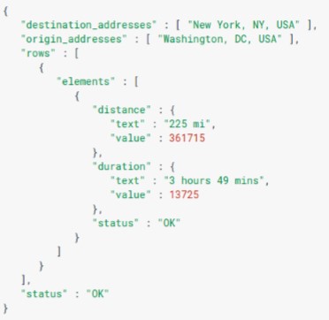
We use the Requests API again to make HTTP calls to Google. Google Maps Distance Matrix API has three required parameters for HTTPS: origin(s), destination(s), and API key. We put the parameters and their corresponding values in the URL. Below, we have an example of the response in JSON (picture from Google’s documentation).
We parse the JSON to extract the “text” value from the “distance” and “duration” “elements” and display them in two separate Tkinter Label widgets. The trip widget is shown in its entirety below.
There are several optional parameters you can pass to the Distance Matrix API that greatly increase its usefulness. First, you can choose to pass in mode, which lets you set the mode of transportation you want Google to use to calculate the distance and duration. There are four values you can pass in: driving (default), walking, bicycling, and transit. If you’re using transit, you can get more specific (i.e. arrival time, what form of transit, etc) using other optional parameters. While we have mode implemented in the trip widget code (defaults to driving), we do not yet have that integrated with voice recognition, so you can’t yet tell our program the mode for which you want the information. That will be a relatively simple add-on; we just haven’t gotten around to it yet.
Another particularly cool optional parameter is traffic_model, which lets you set the assumptions to use when calculating the trip duration given predicted traffic. There are three values you can pass in: best_guess (default), pessimistic, and optimistic. The API looks at historical traffic conditions as well as live traffic when predicting duration, and with this parameter, you can choose which model it uses (average, longer than average, or shorter than average). We don’t yet have this implemented, but it’s on a personal list of stretch add-ons.
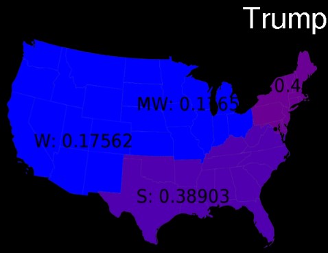
The other new widget we added this sprint is NewsBox. Sung and I created NewsBox as our final Software Design project. NewsBox takes in a search term, pulls tweets from different parts of the country with that term from Twitter, analyzes the positivity/negativity of the tweet and averages it for each region, and produces a choropleth map that shows the positivity/negativity on a scale of blue to red. Whew. That’s always been a hard project to explain succinctly. Here’s a visual explanation of NewsBox as it appears on our GUI (note: we know the text is mostly unreadable and will eventually get around to making it a more visible color). The search term was Trump; the numbers represent the average polarity (scale of 0 to 1, where higher means happier) for the four main regions of the US: West, Midwest, South, and Northeast.
Integrating NewsBox into Spectre was pretty straightforward. I copied the necessary files from NewsBox’s Github repository, and since NewsBox was already saving the choropleth maps to an SVG file, I simply needed to display the SVG file in one of Tkinter’s Label widgets. Unfortunately, SVG doesn’t seem to be a format Tkinter can handle. So, I looked for a way to convert the SVG to a PNG, which I know Tkinter can display. I decided to use CairoSVG, which can convert a variety of image files back and forth, including SVG to PNG. It’s based on Cairo, which is a well-known 2D graphics library. It was incredibly easy to implement -- it only took one line of code that called a function named “svg2png.” It seemed perfect...
But it’s not. I ran into problems when I tried to install CairoSVG onto the RasPi. I think it has something to do with the RasPi not having the necessary graphics libraries (cairo, cairocffi?) I’m still trying to figure out the exact problem, because while NewsBox doesn’t add much value to the user, it would be a fun Easter Egg to have in our smart mirror. For now, NewsBox has not been successfully added to the RasPi. It works well on my laptop...it’s so tantalizingly close to working on the RasPi. Sigh.
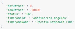
So, moving on to things that do work on the Raspberry Pi, we have two upgraded widgets: clock and news. We’ll start with the clock. Our clock widget has become surprisingly complex. Getting the time is a built-in python function, but we wanted to make it possible to change the timezone, which is not built-in. There was probably a better way to do this, but I was already planning to use Google Maps’ Distance Matrix API and I saw that Google Maps also had a Time Zone API, so I decided to use that to determine the time given a location. It seems pretty straightforward on the surface -- you give the API a location and it returns, among some other information, the raw offset in seconds and the daylight savings time (DST) offset in seconds. Not all countries / time zones practice daylight savings time, so the time difference between two locations might differ at different times of the year; thus, the API returns the DST offset just in case there is one and you want to include that. I’ve included an example of the response in JSON (picture from Google’s documentation).
However, you also need to pass in a timestamp, which is the time you want to convert. Google uses this to figure out if there’s a DST offset. What’s strange about this and a little confusing at first is that the Time Zone API requires you to represent the timestamp as seconds since midnight, 1/1/1970 UTC. That date might seem random, but it’s not. That’s the unix epoch.
I’ll be honest; I’m still a little fuzzy on what exactly that is. I just know that the epoch took place 1/1/1970 at midnight UTC and unix time represents time as a number of seconds since the epoch. The built-in python functions use unix time, but often display it in a different format. Knowing this, we can utilize some built-in python functions to calculate the number of seconds since the unix epoch, given the current UTC, which stands for Coordinated Universal Time. It is the primary time standard used in the world to keep clocks and time synchronized across countries and continents. For reference, it’s five hours ahead of EST.
So, we pass the time since the unix epoch in seconds to the API, and it returns the offsets. If we add the dstOffset and rawOffset, we have the total offset in seconds. Now, we can just add the offset to -- well, what are we offsetting exactly? Again, UTC pops up. The offset is from the UTC, so if we know the current UTC and the offset, we know the time in our specified time zone. There’s one more hiccup however -- the Time Zone API only takes in a latitude, longitude tuple for location, and our user probably won’t know the latitude and longitude of wherever they want the time changed to. So, we also use Google Maps’ Geocoding API to find the latitude and longitude given a location. Like the Distance Matrix API, the Geocoding API is very flexible about the inputs it receives for location, and it uses region biasing when the specified location is too vague to narrow it down to one location. Our code passes the information from the Geocoding API to the Time Zone API, and using the results from that, we can display the time for any given location. Needham is the clock’s default location. For something that happens so quickly, a lot goes on behind the scenes! As far as appearance, the only difference is we now show the day of the week below the time.
Our last improved widget is the news widget. We use the same News API, but we gave the user the ability to change the news source to one of 70 sources. We pull the list of sources from the website and if the user requests something on the list, the program grabs the news from that source instead of the default BBC News. Unfortunately, some of the news sources are harder or nearly impossible to get through voice recognition without more speech parsing (i.e. for ABC News (AU), voice recognition will never pick up the (AU) part correctly to match up). We’re hoping to further improve the widget’s ability to match up requested sources to known sources by parsing the string and speech more (i.e. all lower case, no dashes, nothing in parentheses, etc). It works fairly reliably with several news sources, including The Huffington Post, likely because that has a very distinct name. The widget looks the same as in previous sprints.
Finally, we added more interactions to our GUI. The news, trip, weather, and NewsBox widgets aren’t widgets you probably want to see all of the time. In Sprint 2, they had a permanent spot on the window, but as we added more widgets, the window became increasingly cluttered. Most of these widgets a user would only look at once in the morning, so we decided to hide all of the widgets (other than time) unless called. When a widget is requested, it’s brought into “focus.” This means it’s made visible in the upper right corner. When a new widget is requested, the old widget is made invisible again and the new widget is brought into “focus.”
We do this by using Tkinter’s pack() and pack_forget() methods. Pack(), as we’ve mentioned before, places a widget in some part of a frame (or a frame in some part of another frame or window). Pack_forget() does the opposite. It makes the widget invisible by unpacking it from wherever it was packed. It’s easy to keep the widgets hidden unless brought into focus -- we just pack_forget() all the widgets and then pack() the requested widget in the “focus” spot of the window. The user can do this by requesting a widget or asking the GUI to “show” a widget. Similarly, asking for a new widget or asking to see a new widget will replace the old one.
It’s important to note: requesting a widget and asking to see a widget are different things. Requesting a widget means the user is giving the widget a command (i.e. “get weather for Houston”) whereas asking to see a widget is only asking for the widget to be made visible (i.e. “show weather”). The idea behind this is that you might ask to see a trip, then ask to see a weather, then want to see your trip again without giving it the whole spiel (“show trip” instead of “get trip from blah blah to blah blah”). Getting will still bring the widget into focus; it just does more as well.
But what if you want to see more than one widget at a time? This sprint, we also implemented “pinning.” Pinning a widget means you add it permanently (or rather, until the user asks for it to be unpinned) to the bottom right corner of the screen. If you ask for a pinned widget, it will be brought into “focus” at the top right corner of the screen, but when you ask for a new widget, it won’t be made invisible; it will be moved back to its spot at the bottom right corner of the window. It’s easy to pin widgets (i.e. “pin weather”), and you can theoretically pin as many of the widgets as you like, but your window will start to look pretty cluttered if you do. The order in which you pin the widgets determines the order in which they’re stacked upon each other. The picture to the right shows the right third of the window. The trip widget is currently in “focus,” and you can see the weather widget is pinned in the bottom right corner. These interactions give the user a lot more say in what they see and when.
The focus of Sprint 3 was making our smart mirror smarter. We tackled this problem by cleaning up our code, adding new widgets, improving old widgets, and adding interactions to our UI. The result is marginally prettier but significantly smarter.
Speech Recognition Program Update
For our minimal viable product, we were looking for a way to implement speech recognition that is simplest and easiest to use. We decided to use python SpeechRecogntion module.
The SpeechRecognition module hit every single item in our checklist. It was simple to implement and easy to use. However, it was very lacking on one of the most important fronts: speed and performance. The response time for the speech recognition script implemented using the aforementioned module was about 30 second for individual commands. It took our program a HALF MINUTE to execute a single command.
With our program, everyone became a lovely sloth from Zootopia
Since voice recognition was our program’s main communicative channel between the user and the interface, improving the efficiency and latency of voice recognition was one of top priorities for the software subteam during sprint 3.
The python SpeechRecognition module is a python wrapper for various voice recognition programs and API. In other words, the module that we were using is merely a python program that makes it easier for an end-user to use the speech recognition API and programs. We decided that we would try directly interfacing with a speech recognition api instead of going through an extra layer of program by using a python wrapper. Hopefully, by getting rid of extraneous layer of processing, we would improve the performance of the speech recognition script.
A speech recognition API of our choice was Google Cloud Speech API. One big advantage of directly interfacing with Google Speech API was that we had an access to entire functionality of the API. Instead of only being able to use the functionality that the python wrapper had implemented, we could use everything that we wanted to use from the wide catalog of available capabilities from the Google API. One of those newly available functionality for us was real-time streaming speech recognition. Using this capability, we could get a speech recognition result in real time as an user speaks. This was a perfect use case for us because we had to actively listen for an user input and process an user input as soon as we capture it.
We started our adventure of exploring a wonderful and terrifyingly complex world of a Google API from a sample application of Google Speech API provided by a Google. From there, we added custom functionalities for our user interface.
One of the biggest problems that we had with our previous voice recognition set up was its frequency of misunderstanding important keywords for our voice commands. For example, we use keywords like “weather”, “close”, and “news” to process the user commands, and our previous voice recognition script often misunderstood those words.
With Google Cloud Speech API, we were able to significantly increase the accuracy of understanding voice commands by giving the API a specific set of words that it should look for. We inputted all the command keywords that we are using to the API, and now the API perfectly understands all the voice commands that an user is giving.
Probably, the most impressive improvement is the substantial decrease in processing and response time of the voice recognition script. We were able to bring down the response time from about 30 seconds to 2~3 seconds. Can’t believe it? Watch it in action.
Region biasing → if you give it a common city name, it will use the location of the request to pick which coordinates to return (i.e. Toledo, Ohio vs Toledo, Spain)
May return multiple cities/locations that fits the parameter description, but response might still not include the right one (i.e. there are four Toledo’s in the US alone)
Anderson “Why Am I Here” Ang
Electrical Engineering
National University of Singapore '18 Olin College of Engineering
"Couldn't vote in the US Presidential Elections"
"Did more integration in POE than in mathematics"
Min “Dobby the Shopbot Elf” Jang
Mechanical Engineering
Olin College of Engineering '19
"Sung couldn't vote either and he lives here"
"Spectre actually means a ghost"suminjang4.wixsite.com
Sara “Am I a MechE?”Ballantyne
Mechanical Engineering
Olin College of Engineering '19
"I don't know what I am anymore"
"#engineeringidentitycrisis #HTML #CSS"www.saraballantyne.com
Sung “Just an Intern” Park
Mary's assistant @ Mary Keenan Solutions
Engineering with Concentration in Philosophy and Vim
Olin College of Engineering '19
"I was demoted to an intern after Mary accused me of calling her an assistant"
"I always confuse boss lady and lady boss"sungwoooo.com
Mary “Boss Lady” Keenan
Engineering with Concentration in Computing
Olin College of Engineering '19
"Sung started calling himself my intern and I never stopped him"
"Boss Lady, not Lady Boss" marykeenan.net
Elements
Text
This is bold and this is strong. This is italic and this is emphasized.
This is superscript text and this is subscript text.
This is underlined and this is code: for (;;) { ... }. Finally, this is a link.
Heading Level 2
Heading Level 3
Heading Level 4
Heading Level 5
Heading Level 6
Blockquote
Fringilla nisl. Donec accumsan interdum nisi, quis tincidunt felis sagittis eget tempus euismod. Vestibulum ante ipsum primis in faucibus vestibulum. Blandit adipiscing eu felis iaculis volutpat ac adipiscing accumsan faucibus. Vestibulum ante ipsum primis in faucibus lorem ipsum dolor sit amet nullam adipiscing eu felis.
Preformatted
i = 0;

while (!deck.isInOrder()) {
    print 'Iteration ' + i;
    deck.shuffle();
    i++;
}

print 'It took ' + i + ' iterations to sort the deck.';


 if necessary - they should support a minimum of 4 wires, 2 for each output (to the Motor Shield and the Arduino respectively)
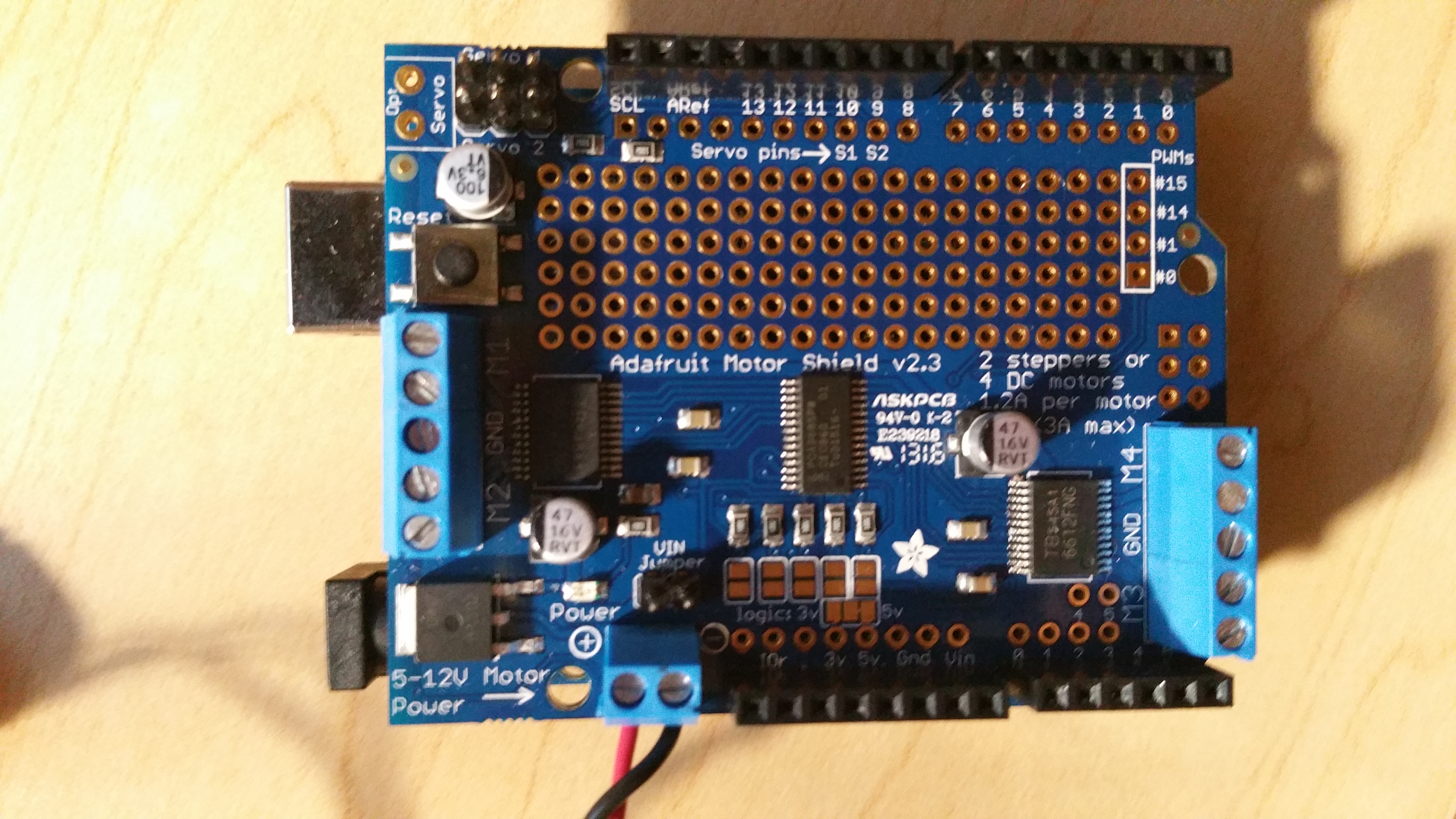
 between the two boards, we will require the use of a USB Type A to Type B connector (see right)