Goals
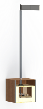
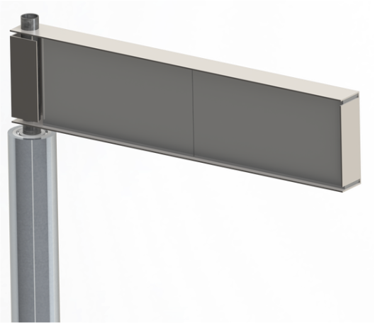
For our mechanical subsystem, we wanted to make a tall (taller than a person, but not taller than llamas, of course) yet sturdy sign post that was able to rotate and possessed a high level of finish.
Process
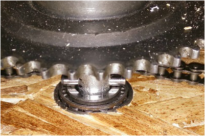
We built two prototypes to identify possible problem areas before constructing our final product. Both were much smaller and not connected to the Raspberry Pi, although we had limited Arduino integration. The way the system works is fairly simple. A stepper motor is controlled by the Arduino. There is an outer PVC pipe which is stationary and structural, nested in the PVC is a smaller steel pipe which rotates and contains the wires for the sign to prevent them from tangling. The stepper motor is connected to the shaft using a chain and two sprockets to be able to more accurately control the amount the sign moves. The double shaft design also separates rotating and non-rotating wires. The non-rotating wires are the wires responsible for control of the microphone and button while the rotating wires connect the screen to the electronics down below.
The base was constructed out of two wood casings, the first is a wire frame style box that houses all of the electronics, motors, and sprockets. It supports the steel shaft on the motor and sitting on top of the inner support is the PVC base, one of the heaviest parts of the sign. The outer box is largely for aesthetic reasons, but also secures many of the power supplies micro controllers, and Raspberry Pis.
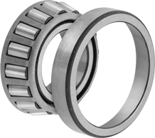
To further prevent tangling wires (which would render them unrecoverable in operation), a limit switch was installed which allows the software component to know exactly where the sign is and ensure that the sign turns roughly equally clockwise and counterclockwise. To keep the shaft up we used a special tapered-roller bearing, which is designed to carry loads while still spinning free. A dowel pin keeps the shaft in place.
Pivots and Challenges
We ran into a few roadblocks.
It was difficult to incorporate the wiring into the mechanical design because of the rotating signpost. We looked at slip-rings but non of them could support our 15(!) wires going up.
The motor shaft and the signpost shaft were not always parallel when rotating, so we could not use gears to rotate the shaft since the teeth of the gears would probably start slipping. To have a more dynamic system we used a sprocket chain combination. This allows more tolerance without slipping. A sprocket chain combination is also way cheaper than metal gears.
Also, we could not attach the stepper motor with glue because of the how hot the stepper motor gets. (This is a good thing; you should never attach a motor with glue in the first place.)
Reflection
As we were building the Cosign, we found that in general the mechanical components took longer to build than expected. We were successfully able to complete it in the time given. We also enjoyed the building process, especially the problem solving aspect. The design and build wasn't particularly challenging, but some of the hurdles we encountered tested us in the way we believe problems should: they were large enough to be challenging, but not so big that they were impossible. This made for a very positive experience.


